This article is part of a series.
View all 17 parts
- Part 1 – The Hunter S. Thompson Board -- Arduino Mega Mini
- Part 2 – Make an ADXL345 Breakout Board
- Part 3 – Mega Mini Motor Shield (M^3)
- Part 4 – My Eagle PCB Walkthrough
- Part 5 – Populating and Programming and APM
- Part 6 – This Article
- Part 7 – HM-10
- Part 8 – Jot
- Part 9 – Homemade Pulse Sensor
- Part 10 – ATtiny Adventure -- I2C on ATtiny 84/85
- Part 11 – ATtiny Bitsy Spider
- Part 12 – Kobold
- Part 13 – Scarab
- Part 14 – The Valdez Mutant -- LPC1114 QFN
- Part 15 – Lab Controller PCB
- Part 16 – Lab Controller v05-09
- Part 17 – Robber Board
Originally posted on www.letsmakerobots.com
I'm posting this collection out of frustration and perhaps defeat. I've been working on several projectss for the last two months, trying to finish something. I'd gotten addicted to that "It works!" moment I think anyone gets when they see a LED blink. Sadly, I feel I've failed at most of these projectss.
The second reason I post is posterity.
I've grown to appreciate failure, given how much I learn from it. Of course, I'd much rather learn from other's failures. So, I figure I'd try to write up all my blunders for others.
The last reason is tactical humility.
I figure I might be able to finish some of these projectss if someone tells me what the hell I'm doing wrong (though, it might take less time if someone tells me what's right).
Alright, enough self-loathing and belaboring.
Contents:
- Arduino heart rate sensor.
- Bluetooth 4.0
- Heatsinking a high-power LED
- XL4432 -- long-range RF
- SMD version of Atmega Fuse Doctor
- Arduino Thermostat
- Raspberry Pi and Remote Compiling
Pulse Sensor Re-Creation -- A Story of Heartbreak:
Pulse Sensor Attempt 1:
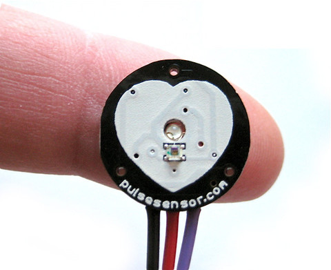
For a awhile now I've been interested biometrics. I figure if my wife ever finishes graduate school and becomes my sugar-momma, then, I'll pursue my pin-headed dope in Experimental Psychology. Developing my own sensors, or at least having an intimate knowledge of how they work would probably help me getting into a program (damn education inflation). So, I've been watching out for open-hardware sensors for a bit, and it seems these guys pulse-sensor was ever increasing in popularity.
As always, I still believe the best way for a dumb-guy like myself to learn smart stuff, is by taking apart stuff the real smart-people make. But being a non-conformist, I avoided trying to re-make their sensor. Still, after viewing other schematics I found ( 1 , 2 , 3 , 4 , 5 ), I decided I'd be such a non-conformist I'd conform and go with the popular sensor.
After a glance, it seemed great; a small lightweight heart-rate monitor that was Arduino compatible. Then, I noticed the design files were put together in Design Spark . "No problem, I thought, I'll just export them over to Eagle, then I can play with the PCB layout, maybe switch those 0603s to 0805s and send it off to OSHPark."
Come to find out there is no easy way to export Eagle files from Design Spark.
New plan, I'll just follow the Pulse-Sensor schematic and re-create the entire board in Eagle (all half inch of it). And that's what I did. I'd post those Eagle files, but, they suck and don't work. I had made several major mistakes.
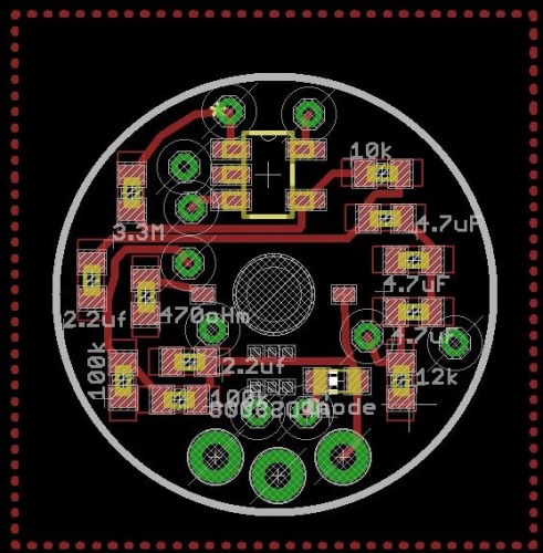
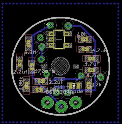
To begin, I had to create several Eagle components for the board. The op-amp, LED, and light-sensor. Respectively, MCP6001 , AM2520ZGC09 , and APDS-9008 . None were a real threat. I made each part according to the datasheets. Then, I strung together the schematic in Eagle, switched to the PCB layout, and threw my pieces down. But for some reason I thought, "I should replace the 0603 passives on this board with 0402s."
I figured, if I could shrink the board even more I'd be happier, right? I mean, smaller is better--so the women say. Well, it was the only thing on this board version I didn't regret.
In the end, the board was sent off to OshPark for a $2.00.
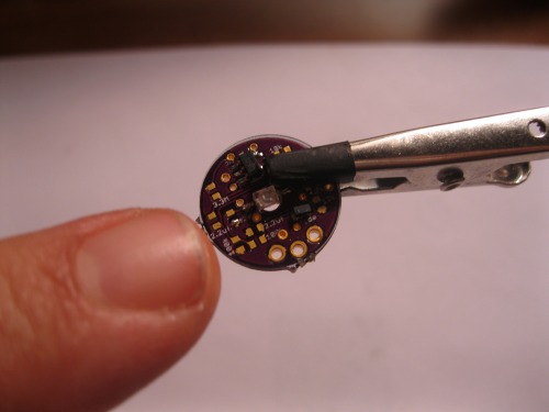
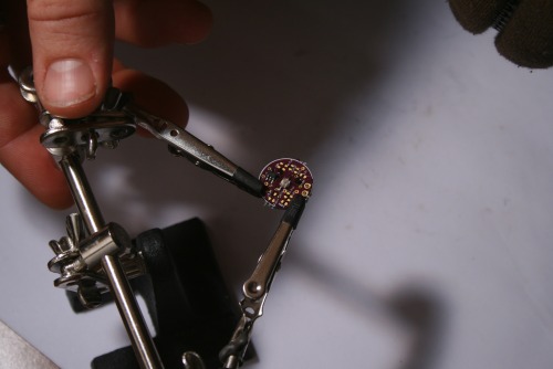
When the post came, as my friends across the lake say, I was excited about the itty-bitty board. Unfortunately, I started my string of disappointments after I populated the board.
 Like I said, I didn't regret the 0402s at all. They all soldered on pretty easy. Though, I think my primary beef with 0402s over 0802 is when it comes to tweezerless soldering. See, when I go to solder 0802s I have this process of tapping one pad with a bit of solder, and taking a resistor for example, hold the 0802's body with tweezers in my left hand while my right hand keeps the solder warm. Then, I simply run one end of the resistor into the pool of solder, move the iron away, then, when the solder cools, let go with the tweezers. To get the other end, I'll put the tweezers down and simply tap the other end with solder.
Voila
.
Like I said, I didn't regret the 0402s at all. They all soldered on pretty easy. Though, I think my primary beef with 0402s over 0802 is when it comes to tweezerless soldering. See, when I go to solder 0802s I have this process of tapping one pad with a bit of solder, and taking a resistor for example, hold the 0802's body with tweezers in my left hand while my right hand keeps the solder warm. Then, I simply run one end of the resistor into the pool of solder, move the iron away, then, when the solder cools, let go with the tweezers. To get the other end, I'll put the tweezers down and simply tap the other end with solder.
Voila
.
I'd try to get a picture of this process, but, I don't have a third hand yet. Though, these folk are working on it.
This doesn't work with 0402s. One, holding the body of a 0402 with tweezers is like a giant trying to tight-rope-walk a piece of dental-floss. But the problem really begins in the second step, when I set the tweezers down to tap the other end, the heat from my iron shots through the little 0402 to the other end, loosening the hardened side, as soon as this happens, the entire 0402 stands on end, hugging my iron. Of course, this ends with me quickly pulling the little guy off with my fingers (not smart, but each 0402 is like $.20).
 A few notes:
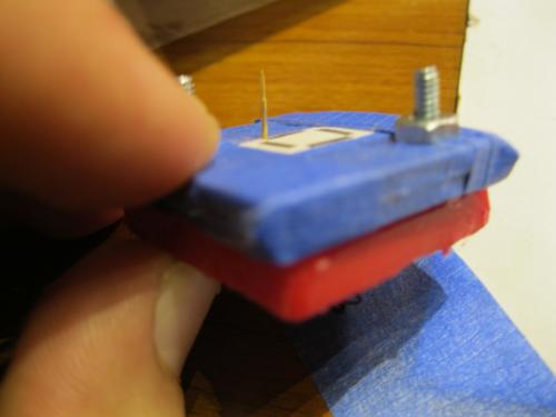
The LED fit through the hole in the PCB, but I was worried the drill wouldn't be wide enough (I guessed a bit).
OSHPark takes non-squarish shapes, though, they charge you as if it were square.
Open-source hardware is not the same as Open-Source (but lacking some key pieces of information) Hardware. I believe the Pulse Sensor is the latter.
The only piece that couldn't be soldered with a solder-iron was the light-sensor. All of it's pads are tucked under the actual component. So, I used the good ole' overturned clothes-iron.
Anyways, once I had all the components in place? I threw on a few wires, attached it to the Arduino, uploaded the sketch, turned it on. And ... smoke.
Waah-waaah.
I'd like to tell you this story has a good end. But, like the title suggests, it's an incomplete work.
I started trouble shooting the board: I checked the wiring, the schematic, the Eagle components I made. I tried 3.3v, different sketches, touching the sensor, not touching the sensor, praying to Cthullu. Nothing. Just pretty smoke.
Finally, I gave up.
(Well, as much as I ever give-up on anything. Stupid obsessive nature.)
Pulse Sensor Attempt 2:
Well, weeks passed and I was working on other projectss, but the little pulse-sensor board kept begging for another chance.
I decided to try again. I'd have no more trying to ignorantly trouble-shoot the thumbnail sized board, so I went back to the designers' original files, downloaded DesignSpark, and pulled up the schematic and board. After briefly examining them I began to realize I was a little off on the board layout. Then it hit me, I could always copy the design manually, it shouldn't take long since I had the schematic already together and the components made.
Well, below is a video of that process :
After I caught the two errors (wrong MCP6001 and disorientation of the APDS-9008) I felt a little better sending it to OSHPark again. Two dollars later I wasn't as sure, but the boards were on their way regardless. While I waited, I jumped on Texas Instrument's website and ordered samples of (what I hoped was) the correct op-amp.
When the boards came in I did something frugal that made me kick myself later: I pulled the components off the old board to put on the new board. It sounded like a great financial strategy at the time, but added more work when I realized my new little board still didn't work . Now, I had to question whether it was the components, the board, or I also ran into this article that scared the crap outta me. Although, it gave me a lot of respect for those guys. Re-soldering 2,000 SMD leds in a night was no small task. And perhaps it welled slight guilt in me since I was working hard to circumvent their more than deserved profit off their $25 sensor .
That's pretty much it: So far. I've not had the time to give her another go, but I will. The next round I'll actually create breakout boards for the main components to make sure my soldering is not the problem. I'm really only concerned with the light sensor, since the pads are practically DFN (no exposed legs). But I hope to have this tied up in the next week to month.
-
.29 ( Digi-Key )
-
Light Photo Sensor: 1.23 ( Digi-Key )
-
LED: .79 ( Digi-Key )
-
0603 Schottky Diode : .50 ( Digi-Key )
-
Passives: ~ 2.50 - Resistors: 1 x 470k, 1 x 12k, 2 x 100k, 1 x 10k, 1 x 3.3Meg - Capacitors: 3 x 4.7uF, 2 x 2.2uF
-
OSHPark Boards : $ .67 (minimum 3 boards, costing $2.00. 3/2.00 = ~.67)
Total (approximate): $ 5.98
HM-10 -- Bluetooth 4.0 Module -- The story of a Broken Breakout
UPDATE (8-3-13)
I've corrected the problem; yes, it was the ground plane under the antenna.
If anyone knows me, they know I'm cheap. But I prefer to think of myself as "resource efficient." This has led me to do a bit of shopping at FastTech . Their stuff isn't as cheap as the eBay, but pretty damn close.
Well, that's a prelude to this story. Awhile back a co-worker's head-phone jack on his phone broke. He said, "Don't you fiddle with that stuff? You should just make me a Bluetooth headset." Externally: Joke-deflected. Internally: Challenge-accepted.
I started looking through different Bluetooth ICs. I mean, why buy Bluetooth ear-phones for under $20 when you could make a set for twice that? Especially, when only takes around a 100 hours of "fiddling" time? Americans are so lazy.
Well, the first IC I landed was this guy: LMX9838 . And it wasn't until I had finished the Eagle part, designed the schematic, and was working on the board did I look at how much it retailed for. Well, I wasn't going to order samples every time I wanted to embed Bluetooth in my projects, besides, isn't Bluetooth 2.0 power hungry?
Well, back to looking through ICs.
And on the second browsing I ran across Texas Instrument's new CC2500 series. Righteous.
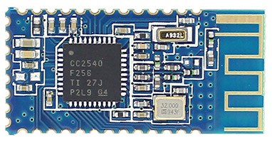
I saw the possibility of making a Bluetooth 4.0 device with this little chip CC2540 . It's a SoC (system-on-chip) with Bluetooth 4.0 capability. Again, righteous.
I ordered several samples of the chip from TI. While I waited on the post I began wading through all the terms: BLE, BT 4.0, Smart Energy, etc. I searched to see if anyone else had already created the schematic, PCB, and firmware that would be needed to drive these little guys. Here are a few discoveries I made.
Hardware:
Here's a complete PCB for the CC2541 , which seems to be optimized for low-power consumption. I will say, the entire chip is pretty well documented on the TI forums, but overall, the hardware aspects are the least.
I downloaded the Eagle files and began ripping off all the unnecessary circuits. (I think there is a lipo charger circuit?) The goal was to bring the board size small enough it would be cheap to print.
But as I got to ripping pieces of close to the antennae noticed how easily it would be to screw the whole thing up. And since I hadn't built my spectrum analyzer yet, I would be stabbing in the dark each time ordered a version of the board.
 This realization on top of all the 0402s and the DFN package, well, I decided I wanted to play with the chip on a completed board, with already installed firmware before I sunk time into a personal development (fancy words for:
I got lazy
).
This realization on top of all the 0402s and the DFN package, well, I decided I wanted to play with the chip on a completed board, with already installed firmware before I sunk time into a personal development (fancy words for:
I got lazy
).
I won't cover the firmware or software, since I took another route and didn't thoroughly Google-search them. But do know, within the collective in the Texas Instrument's cc2500 forums there is almost everything you'd want. Although, be prepared, if you desire to create your own firmware you'll need to brush up on your C and AVR programming.
This brings me back to Fasttech.
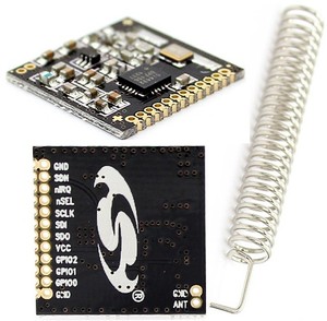
I noticed one day they had these HM-10s on sale. Waahoo! A pre-designed CC2540 board with firmware already created? Firmware that is AT commandable? I bought two.
I figure I could at least get a feel for the chip and see if it was something I really wanted to sink time into developing.
Well, a week later I got these little guys.
 They aren't bad little boards. But, they were little. I tried soldering on jumpers to the ant sized grooves, it didn't go well. I knew to really start playing with the board I needed a breakout.
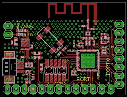
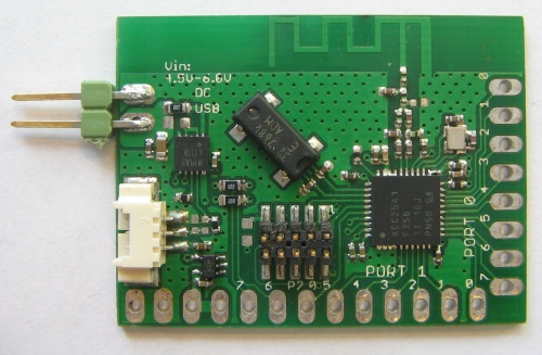
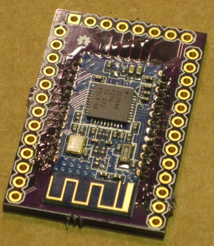
So I made one:
HM-10 Breakout v.9 (don't use, sucks)
When the breakout boards came in I was surprised they worked (I'm usually surprised when something I make turns out :).
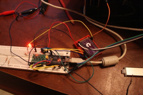
They straddled my breadboard nicely. And it allowed me to play with all the bits of the board I wanted: V, GND, Rx, Tx, and PIO1 (pin for connection-status LED).
Since the little HM-10 operated on 3.3v I carefulIy put it in the breadboard and pulled out my Sparkfun Lilypad FTDI (first huge mistake) to interface with the board's serial.
Well, I couldn't figure out what was wrong; the board would not respond to AT commands (I was using Realterm ). I mean, I had plugged the 3.3v into the HM-10's power, so I know it wasn't getting too much voltage. I even checked it with a multi-meter (about a hundred times).
Well, as those of you who are smarter than me (so all of you?) probably already know: The Sparkfun's Lilypad FTDI is designed to provide the Lilypad with 3.3v, but the Atmega-328-P on the Lilypad is actually 5v tolerant. So why drop the voltage on the Rx and Tx lines? Of course, this wasn't a conclusion I came to for many hours, really, until I started randomly probing the boards with the multi-meter.
Damnit.
Well, there goes $13.98 (yes, I was slow enough to kill both boards).
Discouraged, I ordered two more boards.
You see, when it comes to electronics my driving code is...well, this guy explains it better .
I also bought real FTDI breakout and a logic-level converter . I was tired of frying things.
When everything came in, I took the broken boards off by heating the bottom of the breakout with a heat-gun until the HM-10 was loose. I cleaned the top of the breakout boards with some solder wick. Then, soldered the new HM-10s on.
Video of Soldering the HM-10 to Breakout
I wired the whole mess up on a breadboard and was surprised when I actually got a response in Realterm.
AT
AT+OK
Victory! (hey, I've learned to enjoy even small triumphs)
I had to use specific settings in Realterm to successfully communicate with the HM-10
Under the "Port" tab
- Buad: 9600
- Parity: None
- Data Bits: 8
- Stop Bits: 1
- Hardware Flow Control: RTS/CTS
- Software Flow Control: Receive--Yes, Transmit--Yes
Under the "Echo Port" tab
- Echo On: Yes
- Monitor: Yes
Then, under the "Send" tab typed in my AT commands and hit "Send ASCII":
This worked pretty well. Every time I typed "AT" it shot back, "AT+OK"
So, I started digging for the rest of the AT commands. And dig I did.
Apparently the HM-10 is developed by www.jnhuamao.cn . These folk are somewhere over in Jinan's Hi-tech Development Zone . Anyways, luckily we have GoogleTranslate and I was able to get through several of their current documents. But not before I lost a time on trying to get the module to respond to AT commands no longer supported (like the connection command).
Eventually, I found the current English manual
 The manual answered a lot of my questions. It came with a complete pinout (even a schematic!). After playing with the commands I was re-naming the module, resetting it and running many other needed commands.
Now for a live test.
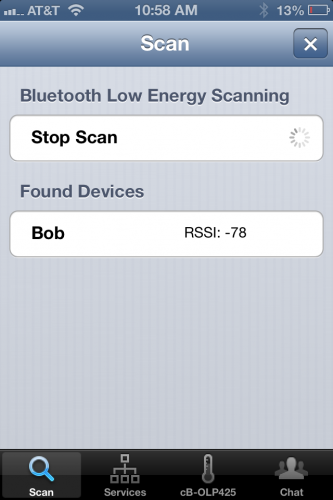
I got my work phone, iPhone 4S, which is equipped with Bluetooth 4.0. I tried using the stock Bluetooth connection found under settings and it couldn't find my little HM-10. I switched to LightBlue and was able to not only find my little module (named Bob), but it connected, and allowed me to send serial data to Realterm! Success.
I thought I was on my way to slapping these little HM-10s on a robot, plugging a Bluetooth 4.0 dongle on my PC, sitting back and letting magic happen. That's not quite how it worked out. I ordered this Bluetooth dongle and when it came in quickly discovered that the drivers needed to provide it with magic powers were not available. I tried it all, TI's tool pack, random internet drivers, shady internet drivers. It simply wasn't going to happen with that dongle.
I figured that's what you get buying the cheapest dongle you can find. So, I switched over to Newegg and bought this dongle, making sure it came with supported drivers.
When I got it in, it still didn't work (I believe this is completely a software issue, so I expect different outcome if I were to play with these dongles on a Linux machine).
I thought, "Well screw it, I could always make a microcontroller, RS232, and another HM-10 into my own dongle."
Um. But I couldn't figure out how to get two of the modules to connect. I set them both up on a breadboard, and they both had the little blinking LED (meaning not connected), but the little guys just wouldn't get it on.
So, on a whim I emailed Jnhuamoa and asked.
Hello,
I'm currently working on interfacing two of your HM-10 modules. I'm having trouble because there seems to be no pairing command. I use "AT+VERS?" and it tells me I'm using version HMSoft V303. Is this old firmware? If it is, is there newer firmware available I could download and write to the cc2540? I've looked through your website and I cannot seem to find any firmware upgrades. But, I only read English, so I'm curious if I've missed it in translation.
I appreciate any help you may give,
--Thomas Brittain
To my surprise, they responded
Dear sir
Thanks you for choose our products.
Between two HM-10 modules, pair and connect process is automic.
You only need to make sure that one of the HM-10 module set to master mode, another is salve mode (use AT+ROLE command), and the TYPE setting of the two modules is the same (use AT+TYPE command) and the PIN number is also same (use AT+PASS command).
If the master module has connected to other modules, please execute AT+CLEAR command first.
Our website have module work flow chart, you can have a look.
:)
Best regards
HMSoft
guocg
But...now what? I mean, I could wire the guys up to an Arduino-bot but it would be one dongle per robot. What I had wanted was several Bluetooth bots per one dongle.
To be honest, I never expected to use the Bluetooth as a bot tether, I was just looking for an application other than my co-workers ear-phones.
After reading the manual some more, and tinkering with the AT commands, I sent another email over to Guocg.
Good sir,
Thank you for your quick reply.
I felt stupid after your instructions. I had the HM-10 paired in less than a minute. A very simple process. Thank you.
But I do have a few others questions. Is there any way to have more control over the connection process? I'd really like to have a micro-controller (PIC, Atmega) in between give the HM-10 very specific commands, which would involve the master connect to several slaves depending on the need of the master. I can see how the PIN could be changed, but would it be fast enough for one master to manage several slaves in real time?
This is the process I'm going to attempt:
1. Setup 3 slaves with unique PINs
2. Setup 1 master connected to a microcontroller.
3. Set master to AT+IMME0 (work when given the command).
3. The micro-controller will pull the HM-10 reset line then give the following commands:
a. AT+CLEAR
b. AT+PINslave1
c. AT+WORK
4. The micro-controller will send a 'X' to slave1
5. Slave1 will have a micro-controller pulling the reset line every half a second or so, unless, it gets a connection with the 'X' string.
I'm not sure of the speed of this process, but I believe it would let me switch between modules remotely. I have read about some of the older releases of the firmware for the module HM-10. Is there still no chance in getting those? I understand now that pairing with the HM-10 modules is very easy, but it also seems very restricted.
Thanks for all the help,
--Thomas
This time, I think I got a blow-off response. That's fair. I'm a hack not an industrial developer.
Dear sir
You shoule make sure that HM-10 modules AT+TYPE vlaue is 1. PinCode set command is AT+PASS.
Best regards
HMSoft
Guocg
 So, no chance on getting older firmware. I started preparing to implement my Atmega & HM-10 team. I strung up the HM-10 on the backpack breadboard of Silas' bot (my son's bot).
I was beginning to get really frustrated with the level conversion problem. I had tried the CD4050 , but found it was uni-directional, meaning I still had to have a converter for the Rx bus (HM-10 and Arduino), or, unplug the HM-10 from the Rx bus every time I wanted to upload a sketch to the Arduino. In the end, I started doing that and used a voltage divider for the Tx line.
That's when I ran into another problem: Range .
More specifically, the lack of range. The little modules would lose connection if more than 7 inches away. Ugh.
Back to trouble-shooting. I couldn't really pin-point the problem. I did find the modules had a power setting (AT+POWEx, X=0-4). But no matter what setting I put the modules on, they didn't have range greater than 7 inches. But I did notice when I was moving the slave around I could get a connection by aiming the master towards the slave. But if I rotated the module, it would lose connection. I didn't want to do it, but I started reading about telemetry.
I can't say I learned anything, though, I did develop a theory. The ground planes I put on my breakout board were screwing with the telemetry.
A second time I breakout the heat-gun and pull the HM-10s off their breakout boards. I get back in Eagle and re-design the breakout to remove the ground planes underneath
HM-10 Breakout v9.3 (untested)
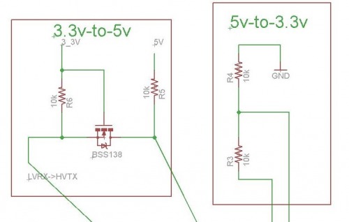
I thought as long as I was going to have the boards printed again, I'd go ahead and add some sort of level conversion. I reviewed a few different SMD chips (CD4050, 74LVC245, TXB0108, etc.) but I found the chip was either uni-directional or overpriced. In the end, I decided on the same design as Ada's and Spark's 4-channel I2C converters.
This design was cheap, scalable, and required little layout room. It was fairly simple, voltage divider from high-to-low, and a tricky little N-Channel MOSFET on the low-to-high. The low-to-high circuit is actually bi-directional (up to a certain speed) but I'm simply using it to raise Tx voltage from the HM-10 to the Arduino, while protecting the HM-10 from uploading a sketch.
**
 **
**
And, that's it so far...sorry.
I've already got my BSS138s and I should get the new boards Monday.
The LED and Heatsink
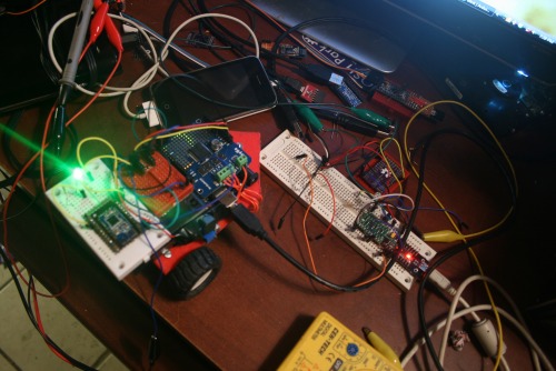
A bit ago I realized I needed to start documenting better and figured a picture was worth a thousand words, so at a 32fps x 1,000, well, in short video documentation should kick-ass (I submit for further evidence chickenparmi 's works :). Well, I got to trying to figure out how I was going to make these videos. That's when I came up with the idea of a piece of wood hanging from the ceiling--feel free to copy this design, it is open-design.
Well, I attached a board with a hole on it so my iPhone could lie there and take videos of whatever my hands were doing. But I noticed there simply wasn't enough light in the hacking hours (after the wife's asleep) to do a proper video. That's when I began looking into cheap high-powered LEDs. They aren't too difficult to work with, the items I ended up needing were.
- PSU ~$6
- LED $4.15
- Heatsink Paste $6.15 (though, reviews say this is better)
- Heatsink $5.48
Total ~ $21.48
This may seem high, but the heatsink paste was used for many other things; I made 3 other LED track lights, and other LED lighting projectss with it, and I've maybe used 5% of the tube. And the PSU has doubled as a work-bench power supply :)
As many other projectss, this one isn't done. The original plan was to add an array of light-sensors to adjust the light as move my hands around, thereby auto-correcting for light imbalances in the videos. That part isn't done.
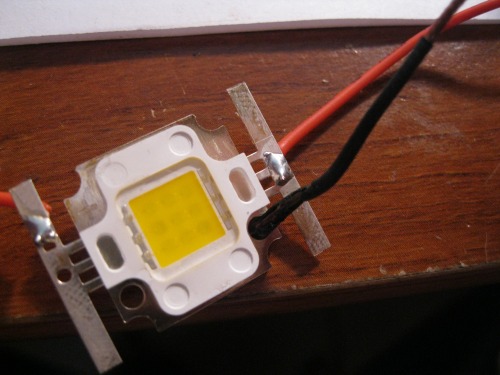
But I jump ahead. When I first started this little projects I had no idea how to work with high-power LEDs. My little ignorant self assumed they were like 20ma LEDs--right? Well, I quickly figured out that heat displacement was the single most important issue. Which is why I ordered a 800 lumen LED 3 weeks before I ordered a heatsink and paste.
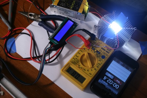
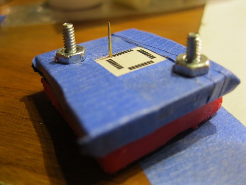
Then, it came to the problem of finding out of my heat sinking was adequate to the massive LED. (I think a 60 watt tungsten produces 800 lume as well? And I know they can cook little cakes--what? It was my sister's Easy Bake , oven not mine.) I digress, so being dyscalculia I was trying to find out if I was heat-sinking proper without delving into higher math. That's when I remembered I had my thermocoupler together from the coffee roaster I built. I strung the coupler together with an Arduino and i2c LCD, giving me a pretty accurate and robust temperature sensor.
I looked for a bit, but I couldn't find the information on the theremal breakdown on the 800lm LED. Eventually, I thought I'd use masking tap to tape the coupler probe against the face of the LED and wire it up (with an appropriate resistor , of course).
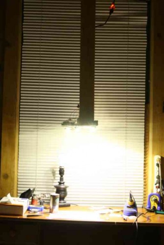
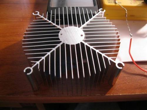
The LED was on 1.5 seconds before it blew up to around 180 F. Uh, ya, I broke out the heatsink. This time, I attached the LED to the heatsink with a bit of thermal paste. I think attached the two screws, which further pressed the LED against the heatsink. Then, I put coupler probe against the face of the LED. I bit off the last of my finger nails and flipped the LED back on. This time, the temperature sensor went up much slower . And after a few minutes stuck around 112 F. Of course, I didn't know if this was beyond the point of thermal breakdown, but I assumed since my own body temperature wasn't far off, and I wasn't exploding, then it would probably be ok. I also touched the face of the LED and was able to leave my finger own for longer than 30 seconds. This I've found to be the most empirically reliable test. With mounting evidence I decided to cut another hole in my board-from-the-ceiling...thing and attach the light. And there we have it. I'll report when I've added the light-sensor arrays.

XL4432 Breakout -- Telemetry is Voodoo
While I was reading about telemetry I discovered these little boards for $3.98 and grew curious if I could do anything with them, other than bricking them. I was very curious about the claim on range, "1000 meters." Even with the BS de-modifier bringing the range down to around 500 meters, that was still something I would love. So I ordered two and made breakout boards for them.
They came in and right away I had macabre feeling that reminded me of the HM-10 boards. Well, I've not played with them enough to know if I've killed them. I go pissed off with my logic-level converter slipping and feeding the board with 5v (a cheap jumper wire came loose from the breadboard).
I stopped what I was doing and re-made the breakout board to include a TXB0108 ( Digi-Key : $2.30). This is the same little chip that's in Ada's 8-Channel Bi-directional logic-level shifter.
XL4432 Breakout Eagle Files ( not yet tested)
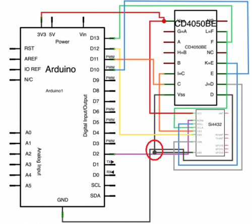
That's really the whole story here, well, except I've been trying to find information on hooking these little guys up with Arduinos for when I do get them wired with a voltage translator. I've found much thus far, but this seems promising. Sadly, I can't figure out how he's got the XL4432 wired up by his poorly drawn schematic(?). Anyone care to give an opinion as to whether those grounds are connected? Logic and CtC both state, "Always, always , connect all grounds." And if I remember my EE schematic lingo, isn't dot on connections most often used when there is an extraordinary node ?
Oh well.
Atmega Fuse Doctor & Pogo Board
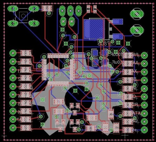
I'm not patient. At all. Which lead me to brick a few Atmega boards ( 1 , 2 ). This upset me, especially since one of those chips was ~$12-17. I had bricked the chips trying to set their fuses in Atmel Studio. Due to the price of these chips I feel it was natural for me to begin looking for a solution. And apparently the Fuse Doctor is one such solution. In essence, it uses the high-voltage programming functions built into Atmel chip.
I thought, "Great. A way to save my chips!" But...I ran into a problem when I saw the board build, it was an etch a home design. And I still do not have pant free of ferric chloride stains. So, I set to re-designing the board into a version I could send off to OSHPark.
I found out the designer had a SMD version of the board ready to go. But, after looking it over I came to the conclusion it would simply be to expensive to print. So, I set out to shrink it.
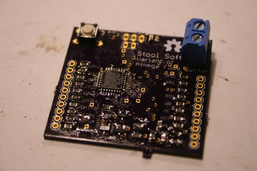
In the end, I printed a board for around $12. But like the rest of the items here, it didn't work as expected. The problem had to do with an extra node I missed, which led to a short-circuit around the voltage regulator. So, I just sliced the trace and was able to at least get pulled up in Atmel Studio and the hex file written to the chip. So, in theory, if I can correct short-circuit, supply it with 12vs, and connect it to the Atmel chips, I should be able to restore them.
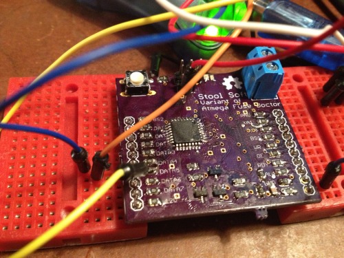
You might see in this image where I'm providing the board with a pre-regulated 5vs through a via. This was to circumvent the short-circuit around the on-board regulator. Also, I had to attach my AVR wires on the other side of the 1k resistors to get the board signature read in Atmel studio.
Here's the materials: BOM .
Kariloy--who has a complete Fuse Doctor by the way--reminded me that even if I finished my board, I probably shouldn't hook it directly to the bricked board. Rather, I'd need to attach to the chip directly. Of course, in the original fuse doctor, this was done by a DIP socket. But I don't use dips... So, I began to think I should just give up on the idea.
Then, I remembered Pogo Pins . I jumped on eBay to see if I could find any pins with a small enough head to fit against a TFQP lead on chips I used. These are the pins I ended up ordering.
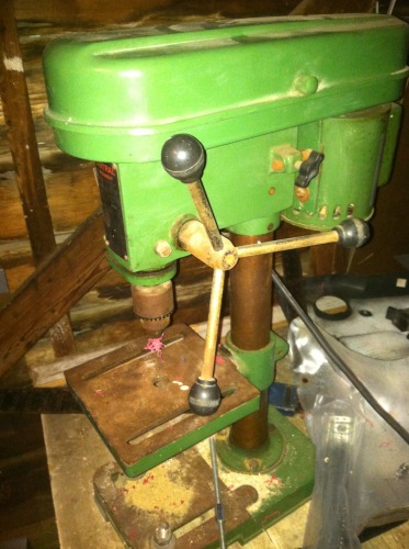
When they came in I was pleased to find they would probably be small enough to fit against a single lead without touching its neighbors. I then started looking for a way to create a jig. I settled on using HDPE (cutting board) I had left-over. I figure I could drill holes in it using the bits I had left over from the Hunter S. Thompson board debacle using OddBot's old drill-press.
<----- OddBot's drill press (thank you OddBot ;).
When I got ready to drill the holes, I got into Eagle and printed out the footprint of a 32-TFQP chip. I cut that out and then cut my HDPE to the same size, making two pieces with enough room for the drill guide in the center. I then drilled two holes in adjacent corners from the other. I put a couple of 4-40 screws and nuts to clinch the two pieces of HDPE together. The idea being, I could spacers between them later and slip the pogo pins through the top, solder the wire on its bottom, then let them rest on the bottom piece of HDPE. Not sure why I state all that....the picture I think explains it.
After I had the hole thing screwed, tapped, and clinched, I ran out to OddBot's drill press, fitted it with the smallest bit I had and tap over one of the pads. I then pulled out one of the small pins and was surprised to find it fit snuggly.
And that's where I stopped, the main reason was not wanting to have to lookup the pinout for the high-voltage serial programming interface on the Atmega-328-P.
Thermostat
 I'm not going to write this up until I do something different then the guy I stole it has done.
My wife, Bek, asked me awhile back to make her a smart thermostat, which I replied, "I'm only at the dumb-thermostat skill-level. Will that do?" She glared, so I Googled for some planes.
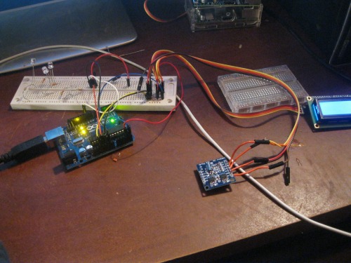
I found this guy's Arduino thermostat and I realized I had most of the parts already lying about.
-- Arduino Uno
-- I2C Real Time Clock
-- I2C LCD
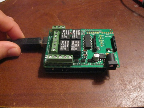
-- Seeed Relay Shield
-- Dallas 1-wire Temperature ( DS18B20)
The idea is pretty simple, the voltage line is tied together on all the legs of the relay shield and the Arduino connects to it. The Arduino reads the temperature from the sensor, checks the time on the I2C RTC, and prints both to the I2C LCD. Also, if the time is correct (after 4:00 PM) it will automatically kick on the AC. I've got it all together and working, just not tied to the AC lines. I was trying to find a way to power it, since all the AC lines are 24v and there is no ground. So, I bought:
- PSU (for laptop): $10.75
- Cord : $1.65
- DC-DC Converter : $1.96
Which gives me 15v, 6A unregulated, or 4.5-40v at 1.6a.
Now, looking back, this projects is more expensive than buying a smart thermostat, and I don't recommend it. The main reason I went with this build was because I owned everything but the temperature sensor and PSU.
Distcc and Gstreamer on Raspberry Pi:
When I began playing with the OpenCV I fell in love. I just felt it has so much to offer us, but I had really kept my tinkering limited to what could be done on the Raspberry Pi. When I finished the little face tracker on the Pi, I knew it would work well as a sensor, but would not approach the level of function I wanted. In short, the Pi simply could not give me the speed I needed. I pulled up OpenCV on my desktop (I wont go into the specifications, just know it's faster than the Pi) and realized pretty quick I'd need to send the video data from the Pi to the desktop if I was to get the results I wanted.
So, I began playing with cheap ways to send video data to the desktop. I started by attempting to use Gstreamer to pipe the video data from the Pi, over my WiFi, into OpenCV on the desktop. Twenty hours later...I realized I was too dumb to make this happen. I began reading.
Put simply, there are so many compatibility issues with this process. I still think it is possible, I just got worn out trying to figure it out. And as I understand it, not all of Gstreamer's development plugins work on the Pi. Then, it was a question of what was going to capture the video (Motion, FFMPEG, etc), and whether one, if any, of these programs liked to play with OpenCV, not to mention, a video pipe that came from the Raspberry Pi. There is no need to say, but I'm going to anyways, it was a mess.
I've built Gstreamer and FFMPEG on the Pi more times than I can count (not many, I count to like 5). This got me to thinking, "This would probably go faster if I could compile these beefy programs on the desktop. After doing a bit of digging through cross-compiling literature, I decided on Distcc . It seems pretty nifty. It is a genuine remote compiler, meaning there are no SD card swapping and mounting, unmounting. Getting it to run on the Pi was the trick.
I won't go through all my wasted time and effort to sort out how to setup Distcc; and, like the other projectss described here, I'm still not done. Though, this guy's post has helped me a lot. I've learned a lot about Bash scripting and have written a script to setup Distcc, mind you, this script doesn't work yet, it's like the rest of the post, incomplete:
!/bin/bash
scriptname - description of script
Text color variables
txtund= $( tput sgr 0 1 ) # Underline
txtbld= $( tput bold ) # Bold
bldred= ${ txtbld }$( tput setaf 1 ) # red
bldblu= ${ txtbld }$( tput setaf 4 ) # blue
bldwht= ${ txtbld }$( tput setaf 7 ) # white
txtrst= $( tput sgr0 ) # Reset
info= ${ bldwht } ${ *txtrst }** # Feedback
pass= ${ bldblu } ${ *txtrst }**
warn= ${ bldred } ${ *txtrst }**
ques= ${ bldblu } ? ${ txtrst }
Sample
echo "$bldred How are you today? $txtrst"
sudo apt-get upgrade -y
echo"$bldred 16% $txtrst"
sudo apt-get update -y
echo"$bldred 32% $txtrst"
wget https://toolbox-of-eric.googlecode.com/files/libiberty.tar.gz
sudo tar -xvf libiberty.tar.gz
cd /home/pi/libiberty
sudo ./configure --enable-install-libiberty
sudo make
sudo make install
echo"$bldred 48% $txtrst"
cd
cd /home/pi
sudo apt-get install cmake -y
echo"$bldred 64% $txtrst"
sudo apt-get install subversion autoconf automake python python-dev -y
echo"$bldred 80% $txtrst"
cd
cd /home/pi
pwd
echo # The remote machines that will build things for you. Don't put the ip of the Pi unless >>.bashrc
echo # you want the Pi to take part to the build process. >>.bashrc
echo # The syntax is : "IP_ADDRESS/NUMBER_OF_JOBS IP_ADDRESS/NUMBER_OF_JOBS" etc... >>.bashrc
echo # The documentation states that your should set the number of jobs per machine to >>.bashrc
echo # its number of processors. I advise you to set it to twice as much. See why in the test paragraph. >>.bashrc
echo # For example: >>.bashrc
echo export DISTCC_HOSTS= "192.168.0.102/16" >>.bashrc
echo >>.bashrc
echo # When a job fails, distcc backs off the machine that failed for some time. >>.bashrc
echo # We want distcc to retry immediately >>.bashrc
echo export DISTCC_BACKOFF_PERIOD=0 >>.bashrc
echo >>.bashrc
echo # Time, in seconds, before distcc throws a DISTCC_IO_TIMEOUT error and tries to build the file >>.bashrc
echo # locally ( default hardcoded to 300 in version prior to 3.2 ) >>.bashrc
echo export DISTCC_IO_TIMEOUT=3000 >>.bashrc
echo # Don't try to build the file locally when a remote job failed >>.bashrc
echo export DISTCC_SKIP_LOCAL_RETRY=1 >>.bashrc
echo >>.bashrc
sudo git clone --depth=1 git://code.opencv.org/opencv.git
cd opencv
sudo mkdir redist && cd redist
sudo apt-get update -y
sudo apt-get install distcc -y
sudo apt-get update -y
echo"$bldred 100% $txtrst"
I'm embarressed to say how much time I spent fiddling with trying to get Distcc to work properly on the Pi. And so much time wasted was my fault. In the end, it was the manual that saved me.
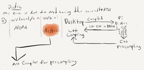
Because I didn't really understand the symlink in this scenario I was having a hard time figuring out how Distcc calls the correct compiler. From what I inferred, a symlink was created to replace gcc, c++, cpp, cc, g++. Then, when any of these were called, the symlink would redirect the data to the remote compiler on the desktop. So, when during first go I had at installing Distcc didn't work because the $PATH variable was incorrect, I thought, "Well, if it's creating a symlink to another compiler, I should just delete the local compilers on the Pi--they're not needed anyway. That way I'm sure I'll get the remote." Due to this stinky logic I issued this command
mv local.compilers localcompilers.old
Sadly, it wasn't until I read the manual (hey, it's a long damn manual) did I discover that a "local pre-compiler is used before the data is sent to the remote compiler." Meaning, every time I disabled the local compiler I done-broke-it.

If the symlink to Distcc comes up first in the $PATH, it calls it as the pre-compiler, then removes it from the $PATH variable. Distcc then calls the the next compiler in the $PATH variable, this time, to it should be the remote compiler.
Given I removed the local, the first compiler it would find it treated as the precompiler, then removed it, leaving no compiler to do the real compiling.
This caused me to get errors stating there was no compiler found.
 I discovered all this waiting on one of my clients to finish a mental-health screening. It definitely confused him when I hit my head against the wall and said, "Son-of-a..."
I'd been digging around in the manual on my phone.
To sum up, I know now that both the real compiler and the symlink to distcc must be in the $PATH variable, they just have to be in the correct order.
But as all the tales of woe here, it is unfinished.