This article is part of a series.
View all 17 parts
- Part 1 – The Hunter S. Thompson Board -- Arduino Mega Mini
- Part 2 – Make an ADXL345 Breakout Board
- Part 3 – Mega Mini Motor Shield (M^3)
- Part 4 – My Eagle PCB Walkthrough
- Part 5 – Populating and Programming and APM
- Part 6 – Incomplete Works
- Part 7 – HM-10
- Part 8 – Jot
- Part 9 – This Article
- Part 10 – ATtiny Adventure -- I2C on ATtiny 84/85
- Part 11 – ATtiny Bitsy Spider
- Part 12 – Kobold
- Part 13 – Scarab
- Part 14 – The Valdez Mutant -- LPC1114 QFN
- Part 15 – Lab Controller PCB
- Part 16 – Lab Controller v05-09
- Part 17 – Robber Board
Originally posted on www.letsmakerobots.com
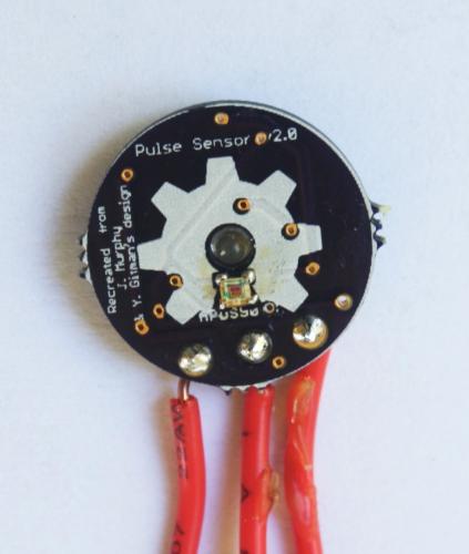
I've been working on re-making the the Open Hardware Pulse Sensor so it'd be easy to send off to OSHPark and to make at home. I'm not sure, but I think I started this projects in March and I've just now finished it.
The bit of encouragement I needed was when hackaday.com put it up as their " Fail of the Week. " I thought I was going to be mature about it. But those four red letters started eating at me, so I gave it another go. Weirdly, I got it working.
I believe there were three problems:
- I had mixed up the op-amps again . In my defense, I've got 5 different ICs flying about in the same package as the op-amp.
- The Arduino I'd been plugging into was sitting on a surface that provided enough conductivity to create noise between the 3.3v pin on the underside and A0, which I was using for the op-amp in.
- Every time I touched the sensor the exposed vias were shorted through my own conductivity. Stupid mineral water.
I've already detailed how I went about making it ; so, I'll try to stick to repeatability.
1. Order the parts.
- Op-amp: .29 ( Digi-Key )
- Light Photo Sensor: 1.23 ( Digi-Key )
- LED: .79 ( Digi-Key )
- 0603 Schottky Diode : .50 ( Digi-Key )
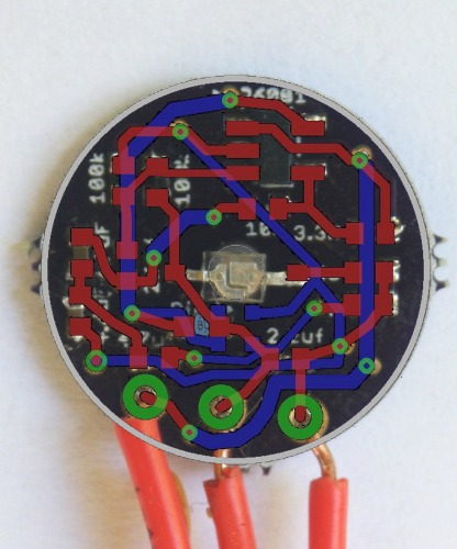
- Passives: ~ 2.50 - Resistors: 1 x 470k, 1 x 12k, 2 x 100k, 1 x 10k, 1 x 3.3Meg - Capacitors: 3 x 4.7uF, 2 x 2.2uF
- OSHPark Boards : $ .67 (minimum 3 boards, costing $2.00. 3/2.00 = ~.67)
Total (approximate): $ 5.98
- Make sure you have theses tools.
- Clothes iron.
- Solder at least .022"
- Flux.
- A soldering iron with a "precision" tip .
- Tacky-putty .
- Precision tweezers.
- Solder the light-sensor.
The light sensor is the hardest bit, so take your time. I put a little bit of solder on each pad with my soldering-iron, then, cover the soldered pads in flux. Next, I attempt to align the light-sensor with the pads as close as possible. After, I put the board with the backside on an over-turned clothes iron. Let the iron heat up until the solder reflows and the sensor is attached.
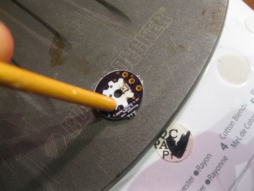
- Flip the sensor and lock it to your surface with tacky-putty to solder the LED, passives, and op-amp. I won't detail this, since my video shows the entire process.
-
Wrap it with tape, cutting a small hole for the LED and light-sensor. (I'll come up with a better solution, and a way it to clip it to your body, on the next iteration).
-
**Wire it up to the Arduino **
Left ---- Middle ---- Right
A0 ------ 3.3v --------GND
-
Run the Arduino and Processing sketches these amazing guys provided.
-
Yell at me if you have problems.