This article is part of a series.
View all 17 parts
- Part 1 – The Hunter S. Thompson Board -- Arduino Mega Mini
- Part 2 – Make an ADXL345 Breakout Board
- Part 3 – Mega Mini Motor Shield (M^3)
- Part 4 – My Eagle PCB Walkthrough
- Part 5 – Populating and Programming and APM
- Part 6 – Incomplete Works
- Part 7 – HM-10
- Part 8 – Jot
- Part 9 – Homemade Pulse Sensor
- Part 10 – ATtiny Adventure -- I2C on ATtiny 84/85
- Part 11 – ATtiny Bitsy Spider
- Part 12 – Kobold
- Part 13 – Scarab
- Part 14 – This Article
- Part 15 – Lab Controller PCB
- Part 16 – Lab Controller v05-09
- Part 17 – Robber Board
Originally posted on www.letsmakerobots.com
This is a little board I made in anticipation of Mr. Bdk6's toolchain for the LPC1114.
This toolchain is amazing. Really, if you are wanting to break away from Arduino / AVR, into the ARM chips, Bdk6's toolchain for the LPC1114 is the way to go.
The Valdez Mutant v04

The chip has ROM boot loader. This allows you to program the chip right out of the box. The programming is done over the traditional serial line. Most ARM chips require a JTAG programmer, which are usually a $50 investment. This leads into a few of my design goals.
A-1. Cheap, cheap ARM entry.
BOM:
- PCB : $2.18 (minimum 3).
- 3.3V LDO Regulator : .56
- 12.5 MHZ Crystal : .74
- LPC1114 FHN302:5 (QFN): 2.80
- SMD DPDT Switch : .44
- 2 x 10uF SMD Tant Cap : .74
- 50-50 RGB SMD LED : .10
- BSS138 : .22
- HM-11: 7.20
Passives are 0402:
- 2 x 22pF
- 3 x 1uF
- 6 x 330 Ohm
- 1 x 1k
- 3 x 10k
- 1 x 20k
- 3 x 470 Ohm
- 2 x 4.7k
- Total for Passives: ~ .22
Total Cost for Board HM-11: $8
Total Cost with HM-11: $15.20
A- 2. Arduino Pro Mini (APM) FTDI programmer to program the LPC1114
After doing a bit of AVR programming I toyed with the idea of getting into the Atmel ARM chips. One barrier to entry is cost, and now that we are down to one income this is a Hannibal to Rome grade barrier. Not only were most of the chips in the $6-20 range, they required a JTAG connector to program. Ultimately, price kept me from building a board around an Atmel ARM chip.
But then Mr. Bdk6 introduced me to the LPC1114. Not only was the chip sub $3 in single quantities (cheaper than the Atmega328P), but it was also programmable with a typical serial-USB interface. I figured, if it was programmable by serial then I could program it with my Arduino Pro Mini FTDI Breakout, which I bought from SparkFun long ago. I did this selfishly, but I assumed a lot of Arduino roboticists here have also switched to the APM as their go to board. I further assumed most would probably have a APM FTDI connector. I took this into account because my goal was to reduce as many barriers in switching from Arduino to the LPC1114, short of writing simple and opaque support libraries.
I'm going to take a brief moment and explain the LPC1114's ISP ROM. The LPC1114 has a built in bootloader, which resides in a ROM block on the chip. When the chip is provided power, either on initial or reset, it runs this bootloader. The bootloader polls PIN 1 on PORT 0 (PIO0_1), if this pin is high or floating, then the bootloader executes whatever is in the program memory blocks. If PIO0_1 is low, then the LPC1114 enters in-system programming mode .
When I discovered this, I got excited. Why not use the DTR/CTS pins to control the ISP? I added it to my design goals.
A few problems:
1. The LPC1114 operates on 3.3v . And don't let your "3.3V" FTDI breakout fool you. They still spit out 5V on for VCC, RX, and TX, at least until you jumper the solder-jumper on the underside. No sweat, I'll add a logic-level translator .
2. There is no existing LPC1114 programming software that controls DTR/CTS. FlashMagic and lpc21isp both use DTR/RTS, while the APM FTDI breakout I have uses DTR/CTS. Stupid dung-beetles in the ointment. I was committed to the idea of using the APM FTDI connector as a "no-modification" way to program the LPC. Thus my toils began.
I started by trying to change the source of the lpc21isp. I was successful in manipulating the source, but the lpc21isp relies on Windows communication protocol drivers, which don't allow for the bit level control of the CTS pin. Damnit.
Still committed.
I started re-rolling my own bootloader using FTDI drivers, which do allow for bit level control of all pins ( FTDI Bitbanging ). Sadly, I got distracted by writing a iPhone app for the HM-10 . By the time I finished the app, Bdk6, who heavily guided me on how to re-roll the programmer, stated he was writing one and would attempt including the features I requested. I figure, "I think this is one time being lazy is in the best interest of everyone." I let Bdk6 write the programmer. :)
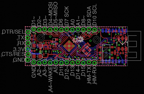
A-3. _Almost _the same size as the Arduino Pro Mini, but with Mounting holes.

Here are the features I pulled:
1. All components are on one side (except for the HM-11). This allows for easy reflow.
2. Small. The Valdez Mutant is the same dimensions as the Arduino Pro Mini, except for the "diving board" area where the HM-11 sits. APM is 18x33mm and the Valdez Mutant is 18x46.97mm
Features lost:
1. I didn't put a reset switch. I was banking on the BLE being able to reset the HM-11 serially (I'll get to that in a bit).
2. A power LED. I decided the RGB LED blinking for the HM-11 could double as a power-led, since the power-rail is the same for the HM-11 and the LPC1114
I added one feature that I've always felt the APM was lacking: Mounting Holes. Some time ago I realized as I continued challenging myself to make smaller and smaller PCB solutions, there gets a point where the board is too small to easily work with. The connecting wires hold it in the air, or pull it off where you set it. I decided I'd add 3mm mounting holes to hold my board in place.
A-4. Wireless Programming Over BLE.
I've always dreamed of hooking up a Bluetooth module to an Arduino and uploading sketches wirelessly. When I discovered the HM-10 I thought I had a real chance (I've not completely given up on the idea), but it took editing the Arduino IDE source. I was able to tweak and compile it, but if anyone who has been through the Arduino IDE source will tell you, it's a friggin mess. But when I went over the design of the LPC programmer interface, I realized the process of flipping bits on the ISP SELECT and RESET lines with the FTDI could be done remotely by the HM-10, using the PIO pins. Hmm. Light bulb.
I therefore set out to design a board that would allow for wireless uploading of programs.
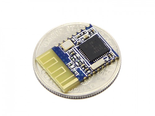
Instead of using my traditional go-to HM-10 , I decided to switch it up and attempt using the HM-11 .
The HM-11 is pretty much the same board as the HM-11, but instead having the 8 or so IO pins, it only has 2. Perfect. One for RESET and one for SELECT.
I thought the HM-11 would allow me to stay consistent with design goal #3: Itty-Bitty.
In theory, this is how the wireless uploading would work.
- HM-11- A sends "AT+PIO30"
- The HM-11- B PIO3 will go low, which sets the LPC1114 ISP MODE to LOW.
- HM-11- A sends "AT+PIO20"
- Then, the HM-11- B PIO2 goes LOW for ~5uS. This will reset the LPC.
- As the LPC comes back up it checks the ISP MODE pin and sees it LOW.
- HM-11- A sends "AT+PIO31" waits ~100mS then sends "AT+PIO21"
- The HM-11- B PIO3 and PIO2 will go HIGH.
- The LPC enters ISP mode.
- The HM-11 PIO2 & PIO3 go HIGH.
- The program is uploaded to the LPC.
- HM-11- A sends "AT+PIO20"
- HM-11- B PIO2 goes LOW, resetting the LPC.
- HM-11- A sends "AT+PIO21"
- HM-11- B PIO2 goes HIGH and the LPC runs the uploaded program.

B-1. Testing
Testing this board was a bit of a bitch. The first version (v02) I printed had several major flaws:
Mistakes on 1st iteration :
- The RX/TX lines were flipped (I swear, I never get that right).
- The CONN pin on the HM-11 was wrong.
- I routed the CTS pin to pin PIO0_2, which is not the reset pin.
- There was a N-Chan flipping for the HM-11 to flip the LPC power. I got rid of that and simply ran a line to the reset (duh).
I quickly corrected these problems and sent the board off again. When the 2nd Iteration came in I wasn't able to test it. No matter what I did I couldn't get it to go into ISP mode. I got pretty harsh on myself, blaming my "crappy soldering skills and dellusions of ability." Then it hit me, I had added 10uF and those take a bit to discharge. I threw the multi-meter on it and sure enough, when I pulled the power from the LPC, then reapplied it (I was using this method instead of the reset line) it took a good 30 seconds for the voltage to drop near nominal. I quickly strung up a momentary switch on the reset line, first time I hit the button it went right into ISP mode. Son-of-a-badger !
Therefore, I consider the 2nd iteration a hardware success.
But there was a big let down. I tried both FlashMagic and lpc21isp to get them to upload across the BLE connection, but they both timed out. Ugh. I guess no wireless download?
Features tested:
- FTDI pinout -- Working -- 50% tested -- (works to provide power and RX/TX work, ability to reset and select mode not yet tested. This will require customer software).
- 5v/3.3v RX/TX converter -- 100% tested -- Working
- DPDT Switch to select HM-11 or USB -- 100% tested -- Working
- Crystal -- not yet tested 0%
- HM-11 -- RX/TX -- 100% tested -- Working
- RGB TX/RX/CONN -- 33% tested -- CONN Working
- LPC reseting HM-11 -- not yet tested 0%
- HM-11 controlling RESET and ISP MODE -- not yet tested 0%
Board Tested and Working: 48%
B-2. Support and Design Files
I'm a hack. I wouldn't even be hacking with LPC1114 if it weren't for the support tools put together by Mr. Bdk6.
Bdk6's work on the LPC1114
- Bdkdev -- Bdk6's LPC1114 toolchain and uploader.
- Valdez Family -- LPC1114 Robot
- Bdkdev LMR Thread (for error reporting).
Some of my work with the LPC1114
- Setting up GCC ARM compiler for LPC.
- Bitbanging with FTDI .
- Re-rolling LPC uploader (incomplete).
Here are some files specific to the Valdez Mutant:
- Valdez Mutant Schematic v04
- Eagle Files -- Valdez Mutant v04
- Pinout Valdez_Mutant_Pins.h (working on).
B-3. Future
Alright, so now what? Um, let's build a robot with it. To do this, I'm going to design a motor PCB with the DRV8837. And I'm hoping that Mr. Bdk6 doesn't mind adding the FTDI reset features and the HM-11 upload features. If he doesn't have time, then I'll probably pick back up my attempt to write my own bootloader.
I did notice a few problems. First, I didn't allow for a VIN pin. This means I'm going to have jumper between a "shield" board and the Mutant. Also, I'm worried about fitting two H-bridges on a PCB as small as the Mutant, the DRV8837 is very small, but the traces to it take a lot of real-estate.
Well, that's it.
A huge thanks to Mr. Bdk6. These tools are amazing; finally escaping Arduino!