This article is part of a series.
View all 17 parts
- Part 1 – This Article
- Part 2 – Make an ADXL345 Breakout Board
- Part 3 – Mega Mini Motor Shield (M^3)
- Part 4 – My Eagle PCB Walkthrough
- Part 5 – Populating and Programming and APM
- Part 6 – Incomplete Works
- Part 7 – HM-10
- Part 8 – Jot
- Part 9 – Homemade Pulse Sensor
- Part 10 – ATtiny Adventure -- I2C on ATtiny 84/85
- Part 11 – ATtiny Bitsy Spider
- Part 12 – Kobold
- Part 13 – Scarab
- Part 14 – The Valdez Mutant -- LPC1114 QFN
- Part 15 – Lab Controller PCB
- Part 16 – Lab Controller v05-09
- Part 17 – Robber Board
Six months ago I bought my first Arduino. Bought it at the Shack. I'd never worked with electronics, but I had to replace a momentary switch on my computer and wanted more. I quickly woke to the Open Hardware community.
A month later, I was reading about making your own PCBs at home. I made my first home board a few days later. It was a motor driver board, and well, it was a mixed success. Definitely not a looker (http://wp.me/p37cuD-3q). But I was hooked. I wanted to do something more sophisticated. And I was spurred on by a story I once heard about Hunter S. Thompson. It was said that he'd often copy pages out of the Great Gastby because he, "wanted to feel for the music of such great words." That's a paraphrase but only cause I didn't want to reread the forward of Fear and Loathing on the Campaign Trail '72 (_once was enough, thanks) ._ Still, the logic seemed sound. So, I thought of how to apply it to electronics.
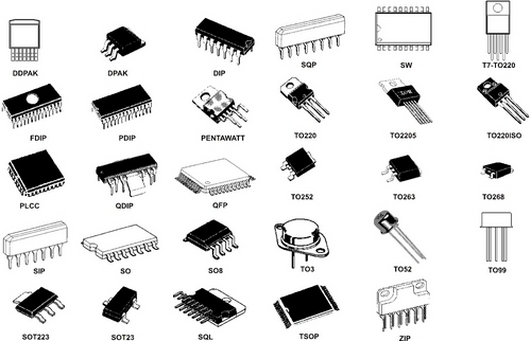
Later, I came across Lady Ada's article on requesting samples from chip makers and I quickly ordered a dozen ICs; I had no clue about any of them--but their names sounded cool. Two weeks later, I had all sorts of random chips sitting around. I thought on what to do with them; when I came across one of the chips I had ordered: Atmega 2560-16UA . It was a nice little TFQP-100 pin chip , um, the size of a quarter. My mind was reeling. "This was the heart of the biggest bad ass Arduino."
I quickly pulled up Arduino.cc to download Eagle's PCB layout for the Arduino Mega . This is where I hit my first snag--um, all that copper board, etchant, and components. Even though I had the main chip it was going to cost a lot to finish Arduino Mega board. And that was if I could. I'd never actually etched a two-sided circuit board. Up to now, I'd only etched one sided and not very well.
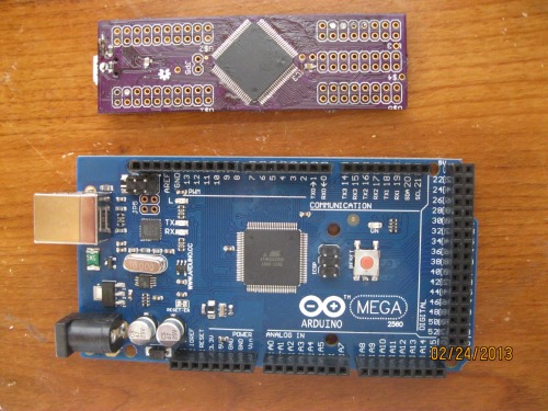
So, I continued to dig for other layouts of the Atmega 2560-16UA that could be used as a Arduino board. That is when I came across this design genuis:
http://jkdevices.com/arduino-megamini
I quickly noticed he provided his design as Open Hardware. To me, this board was magic. It is 3" by 1" and acts exactly like the Arduino Mega. So, I decided, hell or Andy Dick, I was making this board.
Little did I know, there was no Andy Dick, but the other was definitely ahead of me.
1. The Board
I began Goog-searching any information I could find on etching homemade boards (I'll provide my fairly comprehensive link list at bottom). After trying all the different methods, I landed on the fact that the lithography method combined with MG Chemicals was probably going to be my best bet. I began collecting everything I needed.
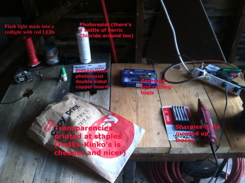
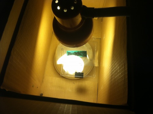
This isn't going to be a guide on homemade PCBs for three reasons: (1) I don't ever want to talk about it, (2) others have already done a much better job than I could, (3) there is a better and cheaper way. Stick with me, there is an exciting cost analysis coming.
Cost of materials to attempt etching a Mega Mini:
- Presensitized 2-sided Copper Board: $.99
- Ferric Chloride: $.99
- Positive Developer: $.20
- Transparencies: $.46
Total per attempt at etching a Mega Mini: $2.65
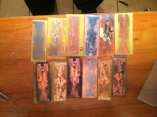 I came to these numbers after 16 attempts. I priced my materials across America, included shipping, cut many boards, and then averaged the costs to come to that final figure. Per attempt, $2.65 was the best I could manage. My problem was several fold. First, I didn't know what I was doing. I understand this will happen: prototyping is more expensive than production units. Second, I picked a mother-of-some-puppies kinda board to etch. The traces are most commonly 8mil, so, it took me about 14 attempts to get to the point where I knew how to etch such small traces. But attempts 15 and 16 revealed to me a hurdle I simply couldn't overcome. I had been relying on FedEx-Kinkos and Staples to print my transparencies and I discovered their print size was off.
I had learned that you can compensate for this in Eagle by changing the "Scale" of your print size, sadly, it only lets you change units to the hundredths place. Any thousandths it will round down. My MegaMini PCB needed to be around 1.025. Of course, this would be rounded to 1.02.
Suck
I came to these numbers after 16 attempts. I priced my materials across America, included shipping, cut many boards, and then averaged the costs to come to that final figure. Per attempt, $2.65 was the best I could manage. My problem was several fold. First, I didn't know what I was doing. I understand this will happen: prototyping is more expensive than production units. Second, I picked a mother-of-some-puppies kinda board to etch. The traces are most commonly 8mil, so, it took me about 14 attempts to get to the point where I knew how to etch such small traces. But attempts 15 and 16 revealed to me a hurdle I simply couldn't overcome. I had been relying on FedEx-Kinkos and Staples to print my transparencies and I discovered their print size was off.
I had learned that you can compensate for this in Eagle by changing the "Scale" of your print size, sadly, it only lets you change units to the hundredths place. Any thousandths it will round down. My MegaMini PCB needed to be around 1.025. Of course, this would be rounded to 1.02.
Suck
Not going to lie. I got depressed. I had sunk much time, money, and passion into etching.
I put the projects on the shelf for awhile. I started working on my bot some. Then, while I was looking at all the neat little things others made on LMR, I noticed in a remark about OSHPark. A while back, I had briefly considered BatchPCB but after I learned the price and tried getting Eagle to produce Gerber files without errors, I gave up. But, I was bored and thought I'd look at OSHPark. I was pretty happy to see I could upload Eagle files directly. Once I got the board uploaded I got depressed again, it was going to be $10.80--oh, wait, that was for three boards. Well, that came to be $3.60 a board. Now, that wasn't so bad. So I sent off for a trio.
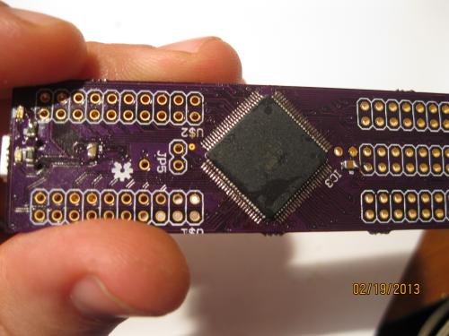
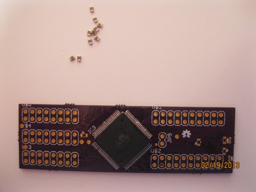
Two weeks later--these amazing little purple boards came in.
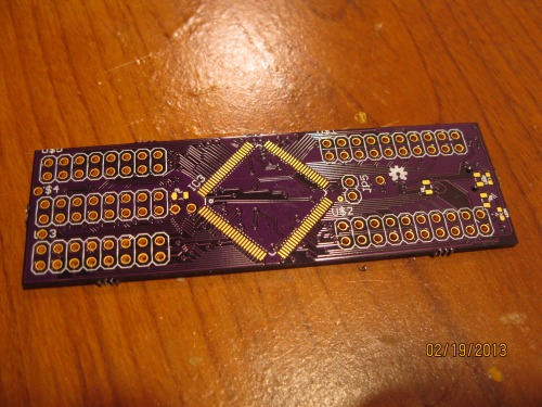
Costs for OSHPark Board: $3.60
Several things jumped right out at me
- The boards already had their vias in place (and this board has around 60+ micro vias).
- It was already lacquered.
- The holes were already drilled.
I started thinking about the trade offs between etching my own and boards or sending them off to OSHPark. I decided the only thing I lost was being off the grid. I was originally in love with the idea of something completely made at home. Yet it occurred to me, even if I etched my boards at home I was still buying ICs. Putting me on the grid. So, there wasn't really anything lost.
Of course, there was also the time trade. I'd gotten my time etching a board down to around an hour. Yet, this didn't include drilling holes, lacquer, adding vias, etc. Also, there was a lesson of virtue creeping over me: Electronics takes perseverance and patience. Also, I'd been noticing that my best ideas were coming while I was waiting for parts. My mind would run through what I had done, then what I could do different. Thefore, the waiting 15 days for a board didn't bother me. I didn't perceive it as time wasted.
As for the price trade off. I only calculated directly used materials for etching boards at home. I didn't include broken bits, markers used, tap, super-glue, etc. I also hadn't included capital needed for home production. Drill bits, drill press, lamps, CFL bulbs, etc. Drilling alone was a big under taking for etching boards at home. I'd already sunk $30 into a used drill press (good price and I've used it for many other things). But the small bits needed were expensive and broke easy. I will say, I learned to break fewer bits by making sure I taped my board down to a block of wood. It was when the board angled and put the bit in a bind that they broke.
My conclusion: OSHPark is awesome.
2. Populating
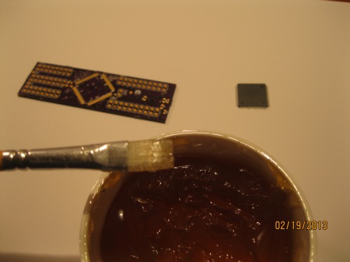
Actually putting the pieces on the board turned out to be the easiest step. I had anticipated this was going to be the hardest, therefore, I had devoted must of my study time to learning how to solder fine SMDs. I knew right away that I wouldn't be able to use my $7 Shack iron on this board. My wife and I allow ourselves $100 a month for entertainment, so I blew one month's on a Hakko FX-888 from eBay. I also bought a T18 CF1 tip . I love this iron. Sturdy and a nifty blue. I felt professional with it.
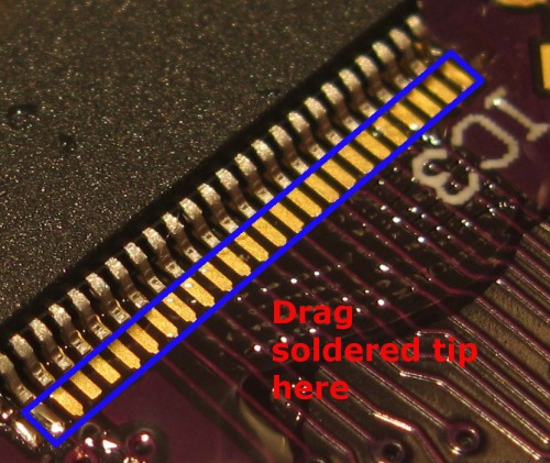
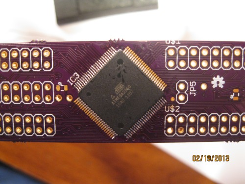
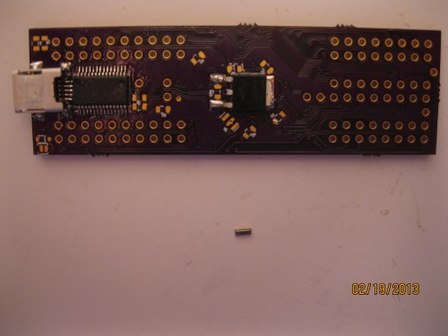
I had read somewhere when populating a SMD you should start with the largest component and work down to the smallest. That's what I did. I started by trying to pin the Atmega chip to its pads. In the end, I used the dragging tip method with plenty of solder flux.
I had also invested in one of these do-hickies so I could check all my pins. I hate the way it looks, but it saved me so many times I don't care.
I put the board on my helping hands and after a lot of flux and around 45 minutes; I learned how to tack the corners with a little solder and then use the drag and drop method. I believe that .022" solder is key here. It allowed me to better control the little solder it takes to connect the pads. One thing I noticed, when using the drag across method, put the solder on your tip and just touch the edge of the pad, not the leg of the pin. As long as your iron is hot enough, the solder will flow on its own up the pad based on the meniscus effect .
Once I got the Atmega in place it only took another 20 minutes to get all the other pieces on the board. No hurdles worth mentioning. Well, the heat slug on the voltage regulator was a little tricky. But I ended up putting solder down on the pad, keeping my iron tip in it, I used tweezers to press the back of the regulator down against it and slide my solder tip out as I did. Not beautiful, but it worked.
The complete parts list for the Mega Mini is follows:
- 16mhz SMD Resonator (Digikey 490-1198-1-ND): $.48
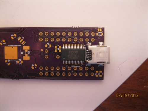
- USB Serial UART 28 SSOP (Digikey 768-1007-1-ND): $4.50
- Mini USB 2.0 (Digikey H2959CT-ND): $1.38
- Atmega 2560-16UA: $12.38-17.00
- 8 x 100nf -- 0805 Capacitors: $.08
- 2 x 10uf -- 0805 Capacitors: $.02
- 1 x 10k Resistor: $.01
- 4 x Uknown Resistors (I used 100k, I believe): $.04
- 5V Voltage Regulator LDO (Digikey NCP1117DT50RKGOSCT-ND): $.49
- OSHPark board: $3.20 ( .Brd files )
- 2 x 0603 LEDs
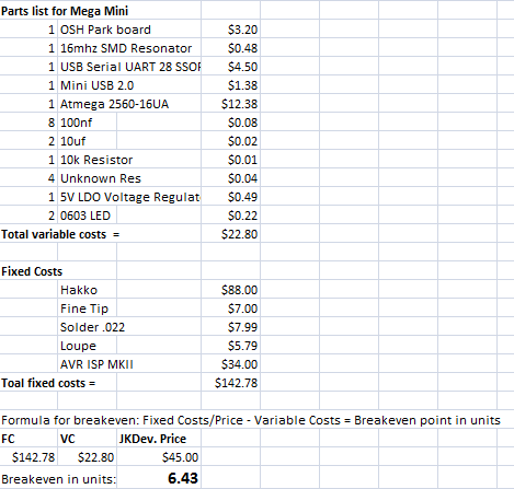
- Total: $22.80
3. Programming It
Last piece soldered! Now I'll I needed to do was plug it in and then it worked, right?
I ran to the computer and plugged my board in. I was thrilled to hear a "Doo-dooh!" USB connection sound and then this pop on my screen.
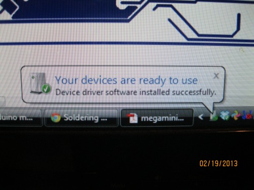
"Your devices are ready to use"
My ass it was!
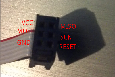
This is where my second hell began. I had bought my AVR ISP MKII to do the programming. After about twenty minutes of going through the pinout I had my interface setup.
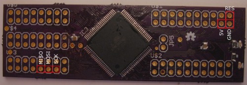
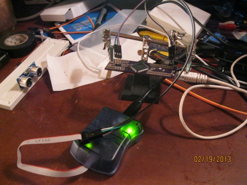 Now that I had it connected. I brought up my Atmel Studio 6. I switched over to the "Device Programmer" selected my programmer, then I selected my chip as "Atmega 2560" (this covers all variants of the 2560). I then hit the "Read" under Device Signature. It shot back telling me there wasn't anything there. I read the voltage, it was fine at 5.1v. I then took the board over and used my hideous spectacles to scoured the board for mistakes I made. One thing I should mention:
I had to guess at a few resistors on the board
. The designer hadn't put their values in schematic. So, I felt for sure that was what it was. Then I looked down to my helping hand clipped to the board--I thought, "Huh. I wonder if something is shorting out on the unhelping hand." Moved the hand. Hit "Read" again. Guess what? If you buy a metal Helping Hands, make sure it's not shorting you board. My board signature was reading. Now, I just had to figure out how to program it. I ran all over Arduino.cc, AVRfreaks, and Lady Ada's forums looking for how to program an Atmega 2560. I found a few posts, but it seemed everyone was more interested in programming Atmega 328 DIP packages. Pfft.
Now that I had it connected. I brought up my Atmel Studio 6. I switched over to the "Device Programmer" selected my programmer, then I selected my chip as "Atmega 2560" (this covers all variants of the 2560). I then hit the "Read" under Device Signature. It shot back telling me there wasn't anything there. I read the voltage, it was fine at 5.1v. I then took the board over and used my hideous spectacles to scoured the board for mistakes I made. One thing I should mention:
I had to guess at a few resistors on the board
. The designer hadn't put their values in schematic. So, I felt for sure that was what it was. Then I looked down to my helping hand clipped to the board--I thought, "Huh. I wonder if something is shorting out on the unhelping hand." Moved the hand. Hit "Read" again. Guess what? If you buy a metal Helping Hands, make sure it's not shorting you board. My board signature was reading. Now, I just had to figure out how to program it. I ran all over Arduino.cc, AVRfreaks, and Lady Ada's forums looking for how to program an Atmega 2560. I found a few posts, but it seemed everyone was more interested in programming Atmega 328 DIP packages. Pfft.
Therefore, out of lack of patience I made a mistake I'll wear to remind me to think three times before acting once. I messed with the fuses. Mind you, I did according to a rather knowledgeable sounding post on Arduino.cc. However, it bricked my board.
Mother-of-some-puppies!
Dante had his Inferno and Purgatorio; I have Etching 8mil and Atmel Fuses.
I went to bed. Got up. Went to work. Helped some homeless people. Tried not to think about my huge blunder. But by the time I got home I knew what I had to do. Originally, I had gotten two sampled Atmega 2560-16UA chips from Atmel. I needed to make the second board. This go, the board took me maybe 25 minutes. But I didn't run over and try to brick it. I waited. I plugged it in and swore to myself not to attempt programing it until I had become an expert on fuses, lockbits, and whatever silly things Atmel had put into such an awesome little chip.
So I read. And read.
Guess what? I'm still just almost as lost.
But I did learn a few things:
- Atmel Studio Driver and AVRDude drivers hate each other. They are like Capulets and Montagues.
- Fuses are written in hex and define the external and internal qualities of the chip. Such as whether or not it has an external clock, or is running on the internal 8mhz.
- No one really messes around with TFQP-100 chips, therefore, I found few people who'd been in my shoes.
- Arduino's IDE automatically sets the fuses when it burns the bootloader. Atmel Studio makes you set them manually.
- Coursera has this class coming up: The Hardware/Software Interface .
In the end, I solved my problem the American way! Gut feelings and dumb luck.
I noticed that I could write the Arduino Atmega 2560 bootloader to the board using Atmel Studio. But I couldn't write it using Arduino's IDE due to the driver conflict. I tried the family's computer. I noticed that the Arduino IDE would act like it was writing the bootloader but would sit with the orange light (meaning it was "programming") on for hours. Then, I noticed something strange after I tried the Arduino IDE to program it on the garage computer running Linux. When I pulled up the fuses page for the board in Atmel studio the fuses had changed. It hit me...maybe the Arduino IDE was successful in writing the fuses but not the bootloader...oh wait! I can write the bootloader from Atmel studio. I ran back to the computer running studio, plugged up the board, and uploaded the bootloader. I said a prayer and plugged just the Mega Mini. I brought up the Arduino IDE and selected the correct COM. I hit "Upload."
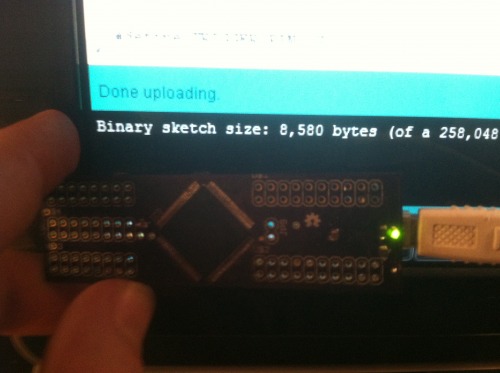
The sketch uploaded. I would have cried but I didn't want to short the board, or, yanno, seem weak and unmanly.
I quickly uploaded my robot sketch and ran off to have an O'Douls.
Lessons learned:
- Etching smaller than 10mil boards is not impossible. But it is not cost effective if time and failed attempts are counted.
- Lithography is the easiest method, with the highest resolution, for two-sided circuit boards.
- OSHPark is a pretty easy and inexpensive way to get quality boards (with holes drilled and vias run!).
- Passion, perserverance, and patience are the virtues of homemade electronics.
- Atmel Studio and AVRDude drivers for the AVR ISP MKII conflict.
- Atmel chip fuses are not toys.
- One should never attempt to use loupe glasses and solder at the same time. You'll burn your hair--trust me.
- A great way to learn something great, is to recognize greatness in others, immitate it, then make it your own. I've already seen how I will change the Mega Mini to meet my needs. I don't really care for FTDI chips on boards. It doesn't make sense to me. They are $4.50. I'd rather put the serializer on the cable. Because I've become initimate with the layout of this board, I know I can redesign it to remove the usb connector and FTDI (saving $5.00 a board).
- If you plan on making fewer then around 7 boards, it is not cost effective to make them yourself. JKDevices sell them for $45.00 and the break even point by my calculations is 6.43 (see chart at bottom). I hope that doesn't discourage anyone. Price is only one way of looking at it. I cannot put a price on everything I've learned in the process.
Plans for future:
- Make a motor shield for the Mega Mini.
- Include M3 (Mega Mini Motorshield) and the Mega Mini into my bot. I believe this will reduce the over bulk of my bot greatly .
- Rework the Mega Mini design and remove the FTDI and USB bits. This will reduce the overall cost of the board by $5.88, bringing the price to produce one down to $16.92. Not too shabby.
- Look into F. Scott Fitzgeralds' take on electronics.
Breakeven analysis:
Links to making homemade PCBs:
- http://www.artemlive.com/cgi-bin/news?c=v&id=750
- http://www.artemlive.com/cgi-bin/news?c=v&id=751
- http://en.electroni-city.com/
- http://www.youtube.com/watch?feature=endscreen&NR=1&v=p2kFazl-aEE (ok introduction to lithography).
- http://www.aplomb.nl/TechStuff/PCB_s/UVsource_PCB.html
- http://sfprime.net/pcb-etching/index.htm
- http://www.jameco.com/Jameco/PressRoom/makeoneetch.html (best introduction to lithography)
- http://www.youritronics.com/diy-printed-circuit-board-using-photo-etching-method/
- http://www.youtube.com/watch?v=8HJrzaW5B3g
- http://quinndunki.com/blondihacks/?p=835 (neat info here, and I think the only lady doing these write-ups besides Limor)
- http://spikenzielabs.com/SpikenzieLabs/Double_Sided_PCB.html
Cheapest micro drill bits I could find:
- https://www.drillbitcity.com/catalogue/10_piece.asp
Links to soldering SMD:
- http://store.curiousinventor.com/guides/Surface_Mount_Soldering/ (My favorite, just ask Grandma Google for the rest; there are many good ones).