
This article is part of a series.
View all 17 parts
- Part 1 – The Hunter S. Thompson Board -- Arduino Mega Mini
- Part 2 – Make an ADXL345 Breakout Board
- Part 3 – Mega Mini Motor Shield (M^3)
- Part 4 – My Eagle PCB Walkthrough
- Part 5 – Populating and Programming and APM
- Part 6 – Incomplete Works
- Part 7 – HM-10
- Part 8 – This Article
- Part 9 – Homemade Pulse Sensor
- Part 10 – ATtiny Adventure -- I2C on ATtiny 84/85
- Part 11 – ATtiny Bitsy Spider
- Part 12 – Kobold
- Part 13 – Scarab
- Part 14 – The Valdez Mutant -- LPC1114 QFN
- Part 15 – Lab Controller PCB
- Part 16 – Lab Controller v05-09
- Part 17 – Robber Board
Originally posted on www.letsmakerobots.com
Videos:
UPDATE: 1/05/13
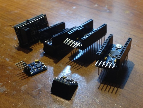
New angle. I finished my ATtiny Bitsy Spider ( ABS ) board and wanted to do something with it. While stringing it together I had thought of replacing the Arduino Pro Mini and the Servo Helper board with the ABS. Costs wise, it will be slighty more expensive ($1.50 or so?) but much smaller and a lot less hassle.
I've read several people had mixed results getting an ATtiny to control servos. Of course, I'm no better. But I was able to get acceptable functionality out of them (i.e., controlling continuous rotation servo speed, direction, braking). Anyway, here's kinda how I approached the servos on the ATtiny 85.
I found several blogs about getting servos to work on the ATtiny but ultimately I used the Servo8Bit library (note, for ease of use I'm linking the "Arduino version" below, not AVR).
It doesn't seem real friendly, but in a hack's opinion, it seems like great code that is incomplete--hope someone corrects if I'm off. The problem I had, and I believe others, was the library using Timer1 for servo timing. The Tiny cores (at least the ones I'm using) use Timer1 for basic functionality, creating a conflict. This presented to me in the inability to use the delay() function. It was simply as if it had not effect. That's when I popped the hood on the library itself. In the header files there is an option for which timer to use. So, I switched it from Timer1 to Timer0. I tried the code again. Great, delay() seemed to work now, but the ability to control the servos was gone. As soon as the myServo.attach(3) was called the servo would spin in with full speed in one direction. Damnit.
I didn't feel like digging through the rest of the library trying to debug something I only half understood. So, I began researching. After a bit, I came upon this thread. Seems this fellow WireJunky was trying to figure out how to do the same, control continuous rotation servos with an ATtiny. At the end Nick Gammon told him he should just create his own timer function.
Anyway, I hacked this code out after reading the thread and was surprised it did what I want. I'm a hack hacking with a hacksaw!
//Basic Jot movement using ATtiny Spider

#include "Servo8Bit.h"
void mydelay(uint16_t milliseconds);  //forward declaration to the delay function

Servo8Bit myServoA;  //create a servo object.
Servo8Bit myServoB;

void setup()
{
  myServoA.attach(3);  //attach the servo to pin PB3
  myServoB.attach(4);
    mydelay(1);
}

void loop(){

            myServoA.write(160);             // tell servo to go to position in variable 'pos'
            myServoB.write(50);             // tell servo to go to position in variable 'pos'
            mydelay(2000);                      // waits 15ms for the servo to reach the position
            myServoA.write(90);             // tell servo to go to position in variable 'pos'
            myServoB.write(90);             // tell servo to go to position in variable 'pos'
            mydelay(2000);                      // waits 15ms for the servo to reach the position
            myServoA.write(50);             // tell servo to go to position in variable 'pos'
            myServoB.write(160);             // tell servo to go to position in variable 'pos'
            mydelay(5000);                      // waits 15ms for the servo to reach the position
    }

void mydelay(uint16_t milliseconds)
{
    for(uint16_t i = 0; i < milliseconds; i++)
    {
        delayMicroseconds(1000);
    }
}//end delay
There are a few issues. It seems my B servo has some jitter in it. It doesn't like to stop at myServoB.write(90). I tried calling myServoB.detach(), then myServoB.attach(3) in a hackish attempt to stop the servo. It'll stop but wont re-attach.
Anyway, even if troubleshooting it doesn't work out I have some work arounds. For example, running the VCC for the servos through a P-Chan that is controlled by the ATtiny, it'd take an extra pin but would allow me to accurately control stopping them. Though, I believe this lack of "centeredness" is due to either a cheap 0805 I used in the conversion or other noisy stuff I have on the PB4 pin.
Of course, to use the ABS as a replacement brain on the Jot, I'lll need to create a star-network with the ABS'es, write a library to control the HMC5883L from the ATtiny, make sure there are no other timing issues, and fit it all in 8k Flash. Ugh. Righ now the code size is around 3k with servo and serial library.
UPDATE: 12/24/13
 Well, I don't know what to say. I think I'm going to take a break from this build for a bit and focus on finishing the Overlord projects with the Dot Muncher.
I discovered what was causing my problems with the NRF24L01. It wasn't the voltage-regulator. It was the 1uF 0805s filtering the regulator. I replaced the unknown capacitors (ones bought off of eBay) with some from Digi-Key that were rated 25v. This fixed the problem and I had the Jot communicating nicely as I had hoped.
Of course, that wasn't the end of the problems. I discovered the HCM5883L board was shorting, I believe, everytime I programmed the board. It's pissing me off. I've burnt four compass boards and two Arduino Pro's over the issue (smoked around $15 in parts). It has something to do with the HCM53883L I2C lines feeding backward through the board whenever the Arduino goes low. It causes the voltage-regulator on the HCM5883L board to pop almost right away. Of course, it does slight damage to other parts of the connected boards. I didn't know it at the time, however, I believe this was the reason the filtering capacitors were damaged, the backward current.
Stuff Burnt on the Pyre of Stupidity -->
That's not the only issue. The code I've got together for the NRF24L01 doesn't play nice with the HCM5338L library.
But I can't tell how to re-write the code in a way they are happy with each while the f'in boards keep burning up. Sigh.
Nevertheless, I think my next step, when I've got my gusto back, will be to make a complete schematic of the Arduino Pro Mini, Little Helper Board, and the HCM5338L. I figure the first two I have schematics for already, and I have enough HCM5883L boards to pull the components off and reverse engineer the PCB.
Still, I'm a little depressed. I'm feel like I'd been better off making the boards myself. At least then, I would know exactly how they are strung together and could only blame myself for issues.
I also feel like Frits needs to put together a "Robotics Fail of the Week" so I can be it's first highlight. Man, even looking at that picture now makes me feel like I suck at life. Oh well, I'm going to list the good stuff I've learned from this.
- Reverse current is a bitch--low-drop diodes are your friends.
- I have put together code that makes the NRF24L01 have closer to Bluetooth functionality. Though, it doesn't like being in the same code as the Wire library.
- Cheap parts are require you be time rich.
- NRF24L01 isn't really meant for streaming data. I knew this to begin, but I didn't understand how it really plays out in the code. The NRF takes a lot of code management. Unlike other devices that are hardware managed or SoC. This makes the NRF highly sensitive to what else your code is doing. In my case, running servos, communicating over I2C, and doing floating point math. As I progress in this build, I feel I'm taxing the NRF's functionality beyond its ability.
- It is better to learn the circuits of all boards connected to yours. It might initially take more time, but in the end save time and money.
- If I fail it something, although looking ridiculous is not fun, documenting the failure makes me feel better. Like it meant something. Even if that something is, "Hey world, I'm an idiot." :)
UPDATE: A Jot of Trouble
I didn't want to float this post until I have something working to update, but I missed writing for a change. I've been working on the little Jot frequently over the last few months. Yet, I keep running into problems. The NRF24L01s are acting silly. One day they work, another they don't. I guess we can't make woman jokes now that Roxanna77 is here? (If you read this Roxanna, just wanted you to know I had to make sure my wife didn't read this post, it'd been hell in my house).
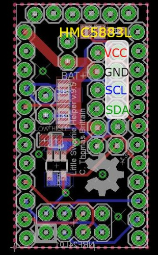
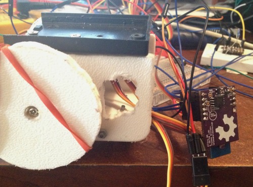
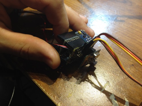
I have reworked the servo board (v.9.5) to include a double 90-degree heade r. One set is to attach the servos, the other is to attach the Compass (HMC5883L) . This was meant to make the hardware more compact, modular, and keep the compass level for a better reading. Oh yah, and I burnt a few HMC5883Ls trying to connect them with crappy braided wires.
Also, I've added solder-jumpers to tie the 3.3 SOT-23-5 voltage regulator's enable pin to either high or low, depending which one I mistakenly buy.
On the top side I've included an SMD voltage divder running straight into analog pin A3. My intention is to allow the Jot to keep an eye on its battery voltage as a way of sensing how "hungry" it is.
I've added a 3.3v pin on the new double 90-header, in case I've a 3.3v sensor elsewhere on the bot. I dunno, I was trying to use all the extra pins I had.
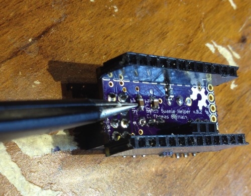
Of course, since I've learned how to tent vias, I've also tented the vias on the board with hope I'll save myself a fateful short or two.
I'll eventually try to replace those bulky headers with what I've affectionaly begun to refer to as " Those short, round headers ." I like these little headers because of how utterly small they are. Of course, they are small but the bulk of their body does not make it through thicker PCBs. This is due to the point flaring closer to where the plastic header is. This flare prevents the short-rounds from sinking through the typical header hole on most boards.
But, I've got calipers, Eagle CAD, and OSHPark, so I made a little library of header holes that will allow these pins to slip neatly through the board and mate with short-rounds on the other side. I sent off to OSHPark for a sample, so I'll report back when I've tested them for effect.
Now, for what has kept me from moving forward with this little damn bot: A cheap voltage regulator .
On my original version of the servo board (by the way, I refer to it as the Little Warmie Helper board or LWH board) I had used a different voltage regulator that cost more. The only difference I found between these were the output, the first I used putting out 200mA and the second 150mA. I really didn't think this made a difference, given what I could find in the datasheet. I know there are passives effecting the power consumption, but it's the only info I could find ( datasheet , pg. 8) The NRF24L01 was using around 11.3mA for the transmitter and 13.5mA for receiver. Even though I didn't know the power-consumption of the passives I believed I was well within the range to use the cheap 150mA voltage regulator. But, experience has proven otherwise.
This is where I ask the professionals to come in and tease me about missing something simple.
The only theory I could invent, given my limited understanding of electronics, is the NRF24L01 only used 11.3/13.5mA in an amp hour, but the burst use exceeds the constant 150mA of the cheap regulator? I don't know. I'm at a loss.
Of course, this is pure speculation. I'm currently out of higher output voltage regulators (I should have some more by the end of the week). But, I can leave the NRF24L01 in place on my LWH board and solder on jumpers to the 3.3v and GND pins and get the NRF24L01 to function properly. This makes me believe the fault lies directly with the inadequacies of the voltage-regulator and not my board design (though, it's inadequacies I'm sure are glaring).
Anyways, this is where I am with the little Jot.
A couple of notes. I have a backup design of the Jot that I'm working to get cheaper than $25, which uses BLE (yes, those HM-10 s I'm in a love-affair). Also, I decided if I was to get serious about the Overlord projects I'd probably do better turning it into a Python module, which I've been doing in silence and is around 90% done. I'll try to have it up before the end of the year. I need to finish several functions.
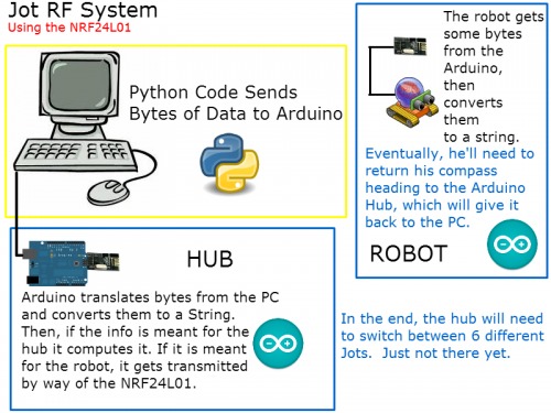
UPDATE: Progress on NRF24L01 code for working between PC, Hub, and Robot.
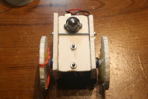
So, here is my attempt at a swarmie build. Not much here yet, simply a personal build log until I get an iteration cheap enough, then, I'll start incorporating them into the Overlord projects.
I have to bow to Bajdi ; those little NRF24L01 take a lot more brainpower than simple ole' Bluetooth. I tried for some time to write my own code that would send and receive bytes to or from the other node. After a little of hair pulling I gave up and started reading other's code. I came across Robvio on the Arduino Forums who had some rather nifty code that I left nearly intact.
#include <SPI.h>
#include "nRF24L01.h"
#include "RF24.h"

RF24 radio(8,7);
// Radio pipe addresses for the 2 nodes to communicate.
const uint64_t pipes[2] = {0xF0F0F0F0E1LL, 0xF0F0F0F0D2LL };

//for Serial input
String inputString = "";         // a string to hold incoming data
boolean stringComplete = false;  // whether the string is complete

//NRF Packages
byte SendPackage[32];
byte ReceivePackage[32];
boolean sending=0;

void setup(void)
{
  //
  // Print preamble
  //

  Serial.begin(9600);
  radio.begin();
  // optionally, increase the delay between retries & # of retries
  radio.setRetries(15,15);
  radio.setPayloadSize(32);
  radio.openWritingPipe(pipes[1]);
  radio.openReadingPipe(1,pipes[0]);
  radio.startListening();
  //radio.printDetails();
}

void loop(void)
{
  //check for NRF received
  NRFreceive();
  //check for Serial received (or filled by NRF)
  Serialreceive();
}

void serialEvent() {
    Serial.println("Event");
  while (Serial.available()) {
    char inChar = (char)Serial.read();
    inputString += inChar;
    if (inChar == '\n') {
      stringComplete = true;
    }
  }
}

byte NRFsend(String NRFPack = ""){
  NRFPack.getBytes(SendPackage, 32);
  radio.stopListening();
  radio.openWritingPipe(pipes[0]);
  radio.openReadingPipe(1,pipes[1]);
  bool ok = radio.write(SendPackage,sizeof(SendPackage));
  if (!ok) Serial.println("NRFerror");
  radio.startListening();
  unsigned long started_waiting_at = millis();
  bool timeout = false;
  while ( ! radio.available() && ! timeout )
    if (millis() - started_waiting_at > 200 )
      timeout = true;
  if ( timeout )
  {
    Serial.println("NRFerror");
  }
  radio.openWritingPipe(pipes[1]);
  radio.openReadingPipe(1,pipes[0]);
}

void NRFreceive(){
  if ( radio.available() )
  {
    //byte ReceivePackage[32];
    bool done = false;
    while (!done)
    {
      done = radio.read( &ReceivePackage, sizeof(ReceivePackage) );
      delay(5);
    }
    radio.stopListening();
    inputString = ((char *)ReceivePackage);
    stringComplete = true;
    radio.write( "1", 1 );
    radio.startListening();
  }
}

void Serialreceive(){

  if (stringComplete) {
    if (inputString.startsWith("T:")) {
      NRFsend(inputString.substring(2));
    }
    if (inputString.startsWith("S:")) {
      Serial.print(inputString.substring(2));
    }

    inputString = "";
    stringComplete = false;
  }
}
The way this code works is much like a software and serial simulated Bluetooth module.
To send serial data it goes like this, you type something with a prefix code, T for transmit and S for serial print, and ending with a newline character (\n).
For example, typing the following in the terminal on module A :
- T:S: My message \n
Will send "My message" to the other module B , then, it will print "My Message" to serial line on the module B .
If you type,
- T: My message \n
This will transmit "My message" from module A to module B , but it will not be printed to the serial line on module B.
I'll let you guys look the code over and tell me if I can improve it for what I'm doing. Right now, I've tested it with some basic Python code to send a serial message to my hub (Arduino Uno and NRF24L01), which relays it to the robot (Arduino Pro Mini and NRF24L01).
Cost to build
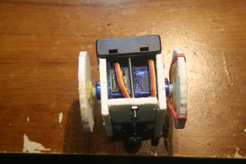
- Tower Micro 9g Servo x 2 : $5.22
- Ball Caster 1/2" Metal x 1 : $3.65
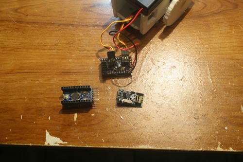
- Funduino (early Arduino Pro Mini): $4.89
- AAA x 4: $1.44
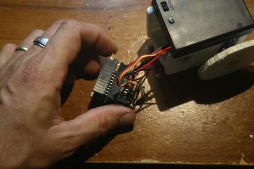
- NRF24L01 x 1: $1.31
- Compass (HMC5883L) : $2.37
- 2-56 Threaded 2" Stud x 2: $1.00
- 2-56 1 1/2" Screw x 2: $.17
- 2-56 Hex Nut x 6: $.23
- AAA x Battery Case w/ Switch: 1.05
- Helper Board:$1.53
- SOT-23-5, 3.3v, .30mA LDO Voltage Regulator x 1: $.57
- 1uF 0805 ceramic capacitor x 2: $.20
- 0805 4.7k resistor x 2: $.03
- 0805 330-860oh resistor x 1: $.03
- 0603 LED ( red , green , yellow ) x 1: $.09
- Right Angle header x 8 : $.05
- Straight Header x 26: $.08
Total (approximate): $23.95
Videos
Designing the build in Tinkercad:
Converting Tower Pro 9g Servo to Full Rotation for Motors:
Cutting Out the Build:
Putting the Pieces Together:
Making the Little Warmie Helper: