This article is part of a series.
View all 17 parts
- Part 1 – The Hunter S. Thompson Board -- Arduino Mega Mini
- Part 2 – Make an ADXL345 Breakout Board
- Part 3 – This Article
- Part 4 – My Eagle PCB Walkthrough
- Part 5 – Populating and Programming and APM
- Part 6 – Incomplete Works
- Part 7 – HM-10
- Part 8 – Jot
- Part 9 – Homemade Pulse Sensor
- Part 10 – ATtiny Adventure -- I2C on ATtiny 84/85
- Part 11 – ATtiny Bitsy Spider
- Part 12 – Kobold
- Part 13 – Scarab
- Part 14 – The Valdez Mutant -- LPC1114 QFN
- Part 15 – Lab Controller PCB
- Part 16 – Lab Controller v05-09
- Part 17 – Robber Board
Originally posted on www.letsmakerobots.com
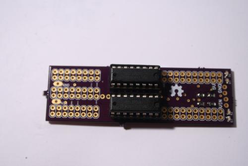
I finally got in my Mega Mini Motor (M3) shield that I designed. I was surprised, after populating the board: It actually worked. The board came about after making the Arduino Mega Mini . I noticed I wouldn't really be reducing the bulk of my bot because of the amount of wiring it would take to get logic to the Arduino Motor Driver shield I was using. Therefore, I set out to design a motor driver shield that would plug right into the MegaMini. I broke out Eagle and some datasheets on an assortment of ICs.
I started out working with the L298D chip, but quickly got frustrated with the way it set on the MegaMini footprint. Plus, the flyback diodes were pissing me off. I had remembered reading that the SN754410 had internal ESD diodes. I started playing with the chip layout and got a board design I was pretty happy with.
I'll attempt a full write up later;I'm pretty mentally fatigued from learning html/css (I know, easy. But as many know by now, cognitively, I'm as slow as a snail on salt.)