This article is part of a series.
View all 17 parts
- Part 1 – The Hunter S. Thompson Board -- Arduino Mega Mini
- Part 2 – Make an ADXL345 Breakout Board
- Part 3 – Mega Mini Motor Shield (M^3)
- Part 4 – My Eagle PCB Walkthrough
- Part 5 – Populating and Programming and APM
- Part 6 – Incomplete Works
- Part 7 – HM-10
- Part 8 – Jot
- Part 9 – Homemade Pulse Sensor
- Part 10 – This Article
- Part 11 – ATtiny Bitsy Spider
- Part 12 – Kobold
- Part 13 – Scarab
- Part 14 – The Valdez Mutant -- LPC1114 QFN
- Part 15 – Lab Controller PCB
- Part 16 – Lab Controller v05-09
- Part 17 – Robber Board
Originally posted on www.letsmakerobots.com
UPDATE: Added info on making SPI programming jig (makes life a lot easier).
UPDATE: Added ATtiny 84 info (though, the post is meant for the ATtiny 85).
I've been non-traditional microcontroller curious for a bit. Then, I had to put a Digi-Key order together for some real cheap stupid stuff (some SOT-23 N-Channels for the LiPo charger circuit) and I thought, "What the hell, let's order some ATTiny 85s." Being cheap like I am, I ordered SMD:
- ATTiny 85 -- SOIC-8 ($1.25 each)
I then ran over to OSHPark and made a little breakout for it:
- ATTiny 85 -- SOIC-8 Breakout board ($.85 for 3, $.28 each)
- ATtiny 84 -- SOIC-14 Breakout board with pogo-pin header ($1.85 for 3).
This brought the price for one ATTiny 85 board to $1.53 each . This is great, since the ATTiny 85 has an internal oscillator up to 8mhz, allowing it run without any passives .
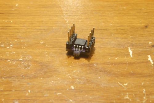
I was pretty excited the day they came in. I soldered them together, put some headers on them, and tossed them into a bread board. I switched over to Goggle and searched how to program these little guys. The first article I hit was the one I eventually used, I just warn you, dear reader, read careful not to miss the bit about ignoring the error. Personally, like the dumb-arse I am, programmed my first little ATtiny 85 a hundred times thinking it wasn't working before I caught the caveat in the instructable:
"It should give the following error twice: avrdude: please define PAGEL and BS2 signals in the configuration file for part ATtiny 85"
This error means you programmed it successfully.
But you all probably got that.
The easiest way to get going with I2C with the ATtiny 85 is using the TinyWireS and TinyWireM libraries for Arduino .
- TinyWireS (this is Rambo's library, he updated the original with onRequest, onReceive functions)
- TinyWireM
To get the ATtiny 84 to work you'll need to add support:
- TineWireS (supporting ATtiny 84)
They were developed to be comparable to the Wire library for Arduino. To install them, just unzip them and place them in your Arduino libraries folder (e.g., C:\Program Files\Arduino\libraries).

(Here's the pinoutfor the ATtiny 84 )
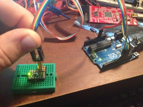
The I2C connections are pretty straight forward:
- Arduino SDA <--- 4.7k Resistor Tied to 5v ----> ATtiny 85 -- PB0
- Arduino SCL <--- 4.7k Resistor Tied to 5v ----> ATtiny 85 -- PB3
- ATtiny 85 -- PB1 <--- 330 Resistor ---- LED ---- > GND
Below is code meant to demonstrate the purpose of this projects. It sets the ATtiny 85 as an I2C slave. It receives data over the I2C line, parses it into an integer, then writes this value of the integer to pin 1 (PB1).
// the 7-bit address (remember to change this when adapting this example)
#define I2C_SLAVE_ADDRESS 0x4

// Get this from https://github.com/rambo/TinyWire
#include <TinyWireS.h>

// The default buffer size, Can't recall the scope of defines right now
#ifndef TWI_RX_BUFFER_SIZE
#define TWI_RX_BUFFER_SIZE ( 16 )
#endif

//Character variable used to echo data back.
char chrSendData;

//Variables used in getting and parsing data.
char rxChrData; //Receives the data.
char rxString[12];  //Varbiable for holding one string of data.
int rxIndex = 0; //Used to index rxString.

//Integer for holding the pwm value received from master.
int pwmValA;

void requestEvent(){
  TinyWireS.send(chrSendData);
}

//Handles receiving i2c data.
void receiveEvent(uint8_t howMany)
{
    if (TinyWireS.available()){
      if (howMany < 1)
      {   // Sanity-check
          return;
      }
      if (howMany > TWI_RX_BUFFER_SIZE)
      {   // Also insane number
          return;
      }

      howMany--;
      if (!howMany)
      {   // This write was only to set the buffer for next read
          return;
      }
      while(howMany--)
      {   //Gets i2c data.
          rxChrData = TinyWireS.receive();
          //Places the characters in an array one at a time.
          rxString[rxIndex] = char(rxChrData);
          //Increment the data array.
          rxIndex++;
          //If a stop character is read, parse the char array and convert it to a single integer.
          if (rxChrData == ':'){
              //This is a low memory form of parsing the char array into an intger
              pwmValA = int(100*rxString[2]+10*rxString[3]+rxString[4]);
              //Prints the parsed value.
              Serial.println(pwmValA);
              //Writes the parsed value to pin 1 (PB1).
              analogWrite(1, pwmValA);
              //Resets the char array index.
              rxIndex = 0;
         }
      }
    }
}

void setup()
{
    Serial.begin(9600);
    pinMode(1, OUTPUT); // OC1A, also The only HW-PWM -pin supported by the tiny core analogWrite
    TinyWireS.begin(I2C_SLAVE_ADDRESS);
    //Sets up the onReceive function (what we do if we get stuff).
    TinyWireS.onReceive(receiveEvent);
    //Sets up the onRequest function (what we do if asked to send something).
    TinyWireS.onRequest(requestEvent);
}

void loop()
{
//Detects a stop sending command.
TinyWireS_stop_check();

//Puts the data we got into a variable to send back for error checking.
chrSendData = char(rxChrData);

}
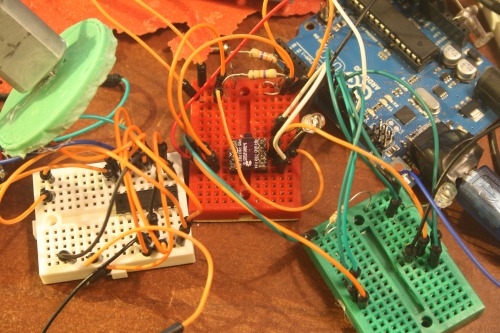
I've also included the code I used on my Arduino Mega, which was setup as the master.
Your setup should not look like this :P
I've got several ideas I'd like to attempt with this setup. But, it is somewhat silly. The I2C reduces the ATtiny 85 to four pins. But one of those is the reset pin (PB5), so really, only 3 usable pins.
Before I started working with the Tiny I was lurking in the shoutbox and oversaw Protowrx chatting about making an ATtiny into a serially controlled motor driver. So, I set to it. I had chosen I2C because I wanted to make a setup like the DRV8830 (Spark fun has a breakout ). Of course, like the numbskull I am I didn't do the simple math before sinking hours into interfacing with a chip.
Most H-Bridge ICs require three pins a motor. Two digital pins for direction and one for PWM. Even cheaping out and using one PWM pin for both motors, that's still five. _And..._the ATtiny 85 has 8 pins. 1 x Power, 1 x Ground, 2 x I2C line, which leaves us with.... 4 pins. Oh wait! One of those is the reset pin and cannot be used without losing the ability to program it without an AVR programmer (which I have, but what a pain in the ass). So! In short, there are 3 usable pins after interfacing with the ATtiny. I'd have done myself a favor if I had remembered an 80s classic .
Still, I've I got it in my head to attempt doing something like this: 2 Pin HBridge control . Only, tying the PWM line together. Not having much luck right now (only spent about 20 minutes, wanted to get this typed up before I forgot crap).
Another idea is to use a Software Serial to send one way communication through the serial line. But it doesn't make much sense, since 4 pins aren't much better than 3, given my intentions.
Ok. In conclusion, I'm not sure why I did this. It really doesn't make much sense, other than the adventure. I'm sure it's one of those things I work out now and I won't find a use until much later. The real killer is thinking about how you can buy a full Arduino Pro Mini on the eBay for $3.45. A little more than double the cost of an ATtiny 85 but triple the pins and utility. Eh!
Making a ATtiny Jig:
I hate breadboarding. Let me admit that. Mainly, it is having wires everywhere, my little dyslexic brain can't keep up. And when I first started working with the ATtiny uCs I found it to be a pain to have to move my little ATtiny's between my full circuit and the SPI programming circuit. So, I thought, "Why not make a SMD programming pad and jig interface?"
Well, here is the crude son-of-a-bitch:
 It's nothing fancy, but it is a time saver.
I put both the interface pads and the jig in my Eagle library.
POGO_PIN_JIG_SPI
POGO_PIN_SPI_PAD
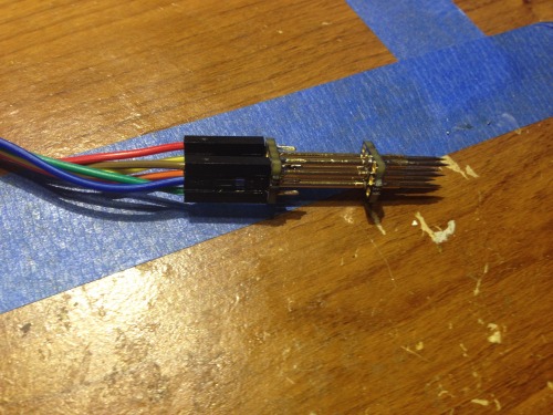
Here is my ATtiny 84 with the pads and the Jig PCB:
Jig ($.60
ATtiny 84 PCB ($1.85)
These are the pogo pins I used:
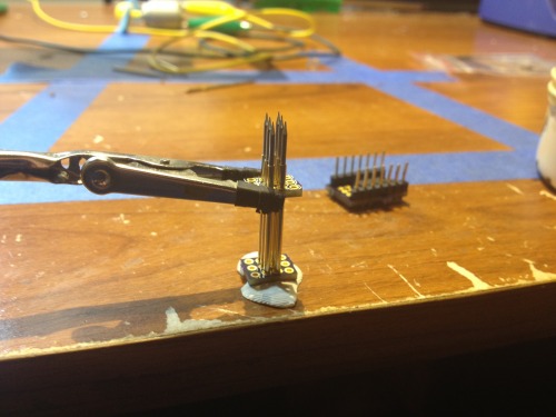
It was not too hard to put together, I set it up something like this. Then, it is all about added flux to where the pins meet the PCB and soldering like you would usual header pins.
 And here it is in action. It surprised the hell out of me, worked exactly like I wanted it.
I'm sure I'll eventually add some stabilizer bars between the two-PCBs and maybe a guide pin to prevent me from pressing the pins in the wrong holes :(
Still, it is MUCH easier than pulling it from the breadboard and moving it to a new circuit. Makes me happy.