This article is part of a series.
View all 17 parts
- Part 1 – The Hunter S. Thompson Board -- Arduino Mega Mini
- Part 2 – Make an ADXL345 Breakout Board
- Part 3 – Mega Mini Motor Shield (M^3)
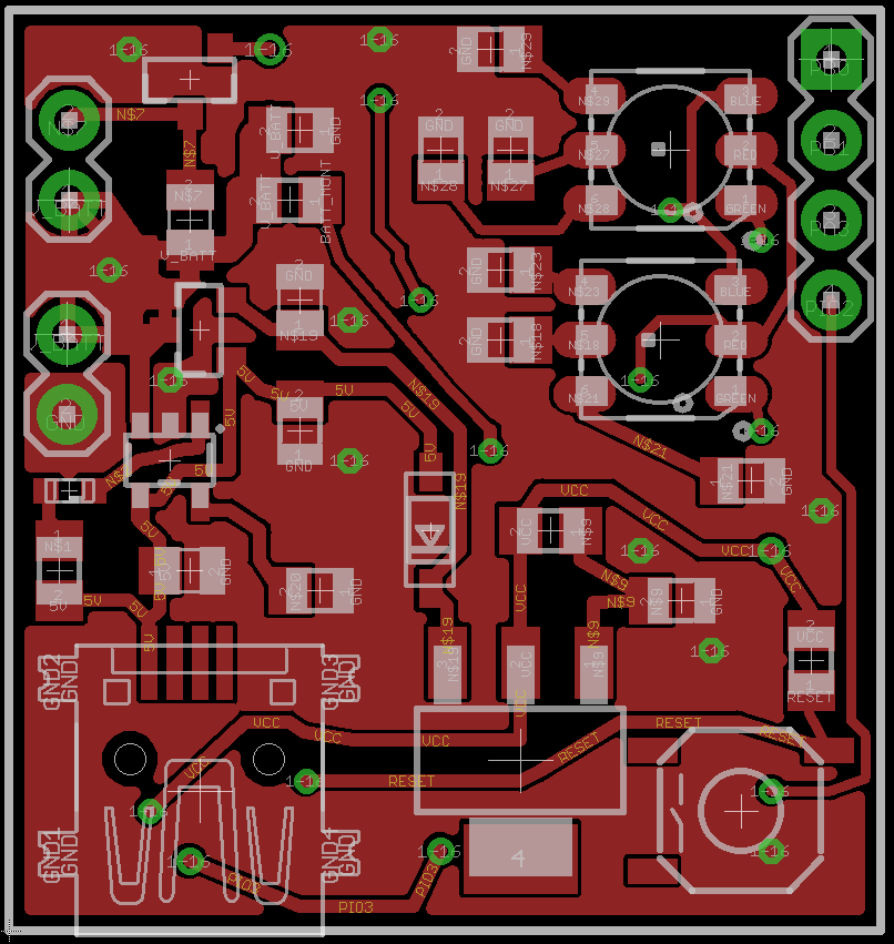
- Part 4 – My Eagle PCB Walkthrough
- Part 5 – Populating and Programming and APM
- Part 6 – Incomplete Works
- Part 7 – HM-10
- Part 8 – Jot
- Part 9 – Homemade Pulse Sensor
- Part 10 – ATtiny Adventure -- I2C on ATtiny 84/85
- Part 11 – ATtiny Bitsy Spider
- Part 12 – Kobold
- Part 13 – Scarab
- Part 14 – The Valdez Mutant -- LPC1114 QFN
- Part 15 – Lab Controller PCB
- Part 16 – Lab Controller v05-09
- Part 17 – This Article
The Robber Board
This board originated with a request from an LPC who was practicing EMDR and wanted to upgrade his feedback machine. He had requested it be wireless and provide both haptic and visual feedback. The whole thing fell apart when he sent me an NDA which seemed typical of real professional level projects. However, it would have prohibited me from sharing anything I discovered, and given the amount I could have made from it, well, it just wasn't worth it. I thought I'd finish the project and share with everyone, since sharing is the greatest form of payment.
Here are some of the features of the board:
- OTA Uploading to an ATtiny84
- An on board charing circuit with load sharing capability ( thanks Zak Kemble )
- Two RGB LEDs to provide visual feedback.
- One unidirectional, motor-driver meant to control a vibration motor.
- Three free pins
My purpose in completing the board is to continue to test my TinySafeBoot BLE uploader:
I'm also in the process of re-writing the uploader to be cross platform, targetting Android, iOS, and Windows 10. It'll be a feat, but I'm thinking I'll center the project around Dropbox. The consumer would:
- Compile an AVR binary using Arduino, Atmel Studio, or AVRDude
- Save the binary in Dropbox
- Lumi3 will then connect to the target device, this could be done from Android, iOS, or Windows.
- Lumi3 would then pull the binary from Dropbox and upload it using the TinySafeBootoader.
Not sure if I can pull it off; wish me luck. And feel free to follow the code base here:

Design Info


HM-11 Setup
A few commands which are required to make the OTA process work correctly
- AT+AFTC3FF -- This command sets all IO pins to go HIGH after connection. This isn't needed for OTA but, since the AVR would be pulled low as soon as it connects, any sketch you have running would immediately be shutdown as the AVR's RESET is pulled low.
- AT+BEFC3FF -- This is like the AFTC command, however, it set IO pins HIGH after the HM-11 is powered. For the Robber, if this is not setup the AVR will stay reset until connected. Initially, I didn't notice this and spent a lot of time trying to figure out what the AVR wouldn't respond. Sigh.
- AT+MODE2 -- this put the HM-11 into "Remote" mode. This will allow AT commands to be sent to the HM-11 after it has been connected, through the BLE connection. This is what allows the commands to be sent to remotely toggle the PIO connected to the AVR's RESET.
A few commands which I think make the connection more reliable:
- AT+BAUD2 -- this sets the communication rate between the HM-11 and AVR to 38400. After testing, this is about the highest speed ATtiny's can for the TSB auto-baud.
- AT+POWE3 -- this raises the radio gain of the HM-11. Power-convseration is not the friend of prototyping.
- AT+GAIN1 -- I think this raises the gain on the HM-11's RX? I'm not sure. The documentation is a little crappy.
Debugging First Iteration
The boards came in from OSHPark. They look sharp--but, it's time to test the board and see what mistakes were made.
Circuits tested:
|Circuit Abstraction|Tested|Pass|Description of Issues| | Mini USB | Yes | 100% | | | MCP73831 | Yes | 100% | Battery Charges. Used a 2k resistor for the charge rate. | | MCP73831 - LED Charge Indicator | Yes | 100% | | Load Sharing | Yes | 100% | Shesh, I love this circuit. Thanks Zak. | | LM1117 -- 3.3v | Yes | 50% | The OUTPUT voltage was calculated based upon 5V INPUT, however, when the USB connection is removed the INPUT voltage is equal to VBAT voltage. In short, the output is ~3.29v when connected to USB and 2.9v when running on battery. This will drop even more when the battery discharges. I've selected a fixed VREG to drop in later ( NCP186-AMX330TAG ). | | Tacit Reset Switch | Yes | 75% | The reset line was being pulled HIGH with a 10k resistor. This might have been causing issues. It was removed for the time and will be re-added if needed. | | ATtiny84 -- Wireless UART Connection | Yes | 85% | I cannot get the ATtiny84's TSB bootloader to respond. I've tried both wireless TSB HELLO and jumpering directly to the UART. No response. I'm currently waiting on a SOIC-14 ATtiny AVR programme r to arrive to more easily troubleshoot the ATtiny84 chip. One thing I'd like to test is the BROWNOUT fuse setting. It seems like this fuse was set different than usual. Also, testing the UART on the naked chip would be helpful. Update: Ok, not sure what happened to the chip, but apparently I killed it? Regardless, when a new one was programmed and swapped out using a heat gun--the new one worked like a charm. I've provided more details below.| | Battery Voltage Monitor | No | | | | RGB LEDs | No | | | | HM-11 Reset of ATtiny84 | Yes | 0% | BAD IDEA! I've wasted a lot of time because the program I uploaded was sending the HM-11 RESET pin HIGH and LOW. This made it difficult to re-program, since the HM-11 would lose connection before the upload finished. Dear lord, what was I thinking? | | Vibration Motor | Yes | 100% | It doesn't work too well when powered by USB alone. Probably need to get a lower powered vibration motor. Also, I don't like the wire connections. They get all tangled and pull off. It'd be better with a PCB mounted vibration motor. |


Debugging Wireless UART Connection
When the ATtiny84 and HM-11 combination were tested using Lumi the Robber board failed to handshake. It was disheartening. The connections were double checked, routing was checked, jumper wires soldered on, ATtiny84 fuses checked, even checked the TSB build used. Nothing. Frankly, the reason it was such a problem to troubleshoot was lack of foresight in prototyping. Here are a couple things which should be in every prototype:
- Jumpers. This is especially true if there is a UART connection. They just beg to be miswired. By providing solder-jumpers the UART connection can be tested a device at a time; ATtiny84, then, HM-11
- Test points. Gah, this is a no-brainer, but in inevitably there end up being leads soldered on at the most precarious place.
Back to the Robber board issue. I got wore out trying to do stuff like this:

The wires kept popping off, they'd need to be resoldered, then pop off again. Finally, I broke down and bought a SOIC-14 AVR Programmer . Dear lord, where has this thing been all of my life? Instead of taking two hours of setting up a chip, wiring leads, and programming it, I was done in about 10 minutes. If you like SOIC ATtiny85/84 chips, get one!
Here's an action shot!

SMD RGB LED
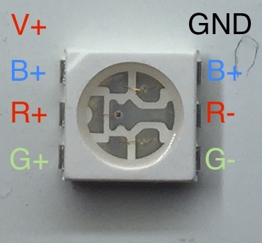
There was trouble testing the SMD RGB LEDs. During the solder-desoldering process the voltage traces for the green LED came off the board. However, this shouldn't affect the second LED--but for some reason the green channel on the other LED is the only one working properly. The red and blue do not seem to be lighting up.
I thought I'd take a moment and diagram the SMD RGBs I'm using, as I can't ever seem to get directionality correct.
2017-12-24 -- v3
I've almost finished testing the Robber board v3. A few changes:
ISP Key
I've added a special ISP header to the board. It works with Tiny AVR-ISP pogo-pin programming adapter
It's a bit of a pain to solder, but it's pretty darn sweet once it's in place. Of course, the header is backwards. More on that later.
