
This article is part of a series.
- Part 1 - The Hunter S. Thompson Board -- Arduino Mega Mini
- Part 2 - My Eagle PCB Walkthrough
- Part 3 - Mega Mini Motor Shield (M^3)
- Part 4 - My Eagle PCB Walkthrough
- Part 5 - Populating and Programming and APM
- Part 6 - Incomplete Works
- Part 7 - This Article
- Part 8 - Jot
- Part 9 - Homemade Pulse Sensor
- Part 10 - ATtiny Adventure -- I2C on ATtiny 84/85
- Part 11 - ATtiny Bitsy Spider
- Part 12 - Kobold
- Part 13 - Scarab
- Part 14 - The Valdez Mutant -- LPC1114 QFN
- Part 15 - Lab Controller PCB
- Part 16 - Lab Controller v05-09
- Part 17 - Robber Board
Originally posted on www.letsmakerobots.com
- UPDATE: 7/6/14 – Silkscreen corrections.
- UPDATE: 6/1/14 BOM Corrections.
- UPDATE: 4/2/14 – Corrected information and linked the new breakout board, v.9.9
Also, this fellow is working on open-source firmware for the HM-10.
UPDATE (2/514): I split this post, since it’s getting a little sluggish. I’ve updated the breakout board versioÂn v.9.9, have instructions for updating the firmware, and added some research notes on a pseudo-Star-Network.
UPDATE (11/23/13): I’ve added research notes on networking the HM-10s and an ATtiny 85 serial filter (at bottom).
OLD:
I know there are few Bluetooth 4.0 and Arduino solutions coming out. Redbear Labs’ BLE Shield, the BLEDuinoe Kickstarter projects, and the Bluegiga Shield. But I didn’t really like these due primarily to the price:
- Redbear’s Mini: $39.95 (Note: This is a uC and BLE combo).
- Redbear’s Uno Shield: $29.95
- BLEDuino: $19.95 (if part of Kickstarter)
- Bluegiga Shield: $69.95
These are out of my price range for a single module. So, in the end, I created a breakout for a cheap module and got it interfaced with the Arduino for approximately $10.03 a module. Although, this price will be higher if you don’t buy components in bulk.
Here’s a Video Summary:
Now, I’ve not interfaced these with iOS or Droid devices, they are simply a Bluetooth 4.0 solution for a wireless serial connection. I’ve interfaced these devices in a limited way with iOS. I used the LightBlue App on my iPad Mini to open a rough serial interface. Though, I’ll probably do this later with Jellybean 4.3’s Bluetooth 4.0 API. UPDATE: I’ve discovered jnhuamoa provides sample iOS 7.0 interface code for the HM-10.
Proof of Concept Video
Now, if only I had the $99 to pay for an App store publisher license, I’d make us all a nice little robot interface :)
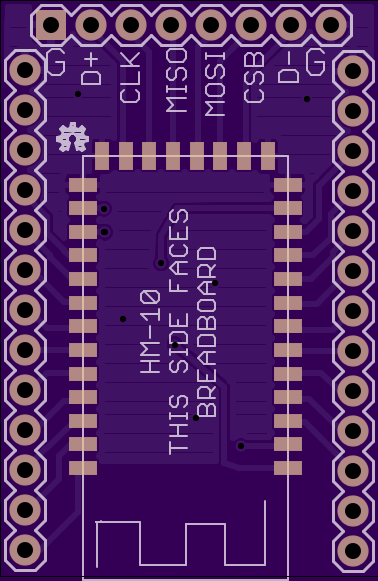
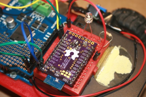
The modules I used were these HM-10’s. I won’t go into making the breakout board, since I did that already. I will state, though, the last iteration of the breakout boards I made had mistakes that I was able to correct for home use, and I’ve corrected them in the Eagle files I’ll put up, so the board files I put up are untested, though, they are on the way and when I’ve confirmed they work I’ll post a confirmation. Also, the images I have of the boards I’m using are different, since I corrected the board files. UPDATE: It has come to my attention the traffic LEDs on the RX/TX lines are always on due to the level converter pulling the lines high. The board still functions as intended if the LEDs are left unpopulated.
Ok. Let’s make a breakout…
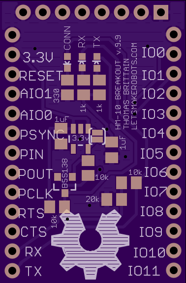
1. This is the v .9.9 of my breakout. I do not swear it is bug free, but it seems stable. Working traffic LEDs and it uses a linear voltage regulator:
OSHPark link: Breadboard Footprint (~$6.35 for three)
Github: HM-10 Breakout Eagle Files
2. Order the boards from OSHPark.

3. Order the SMD pieces you’ll need.
The bill-of-materials (BOM):
- HM-10 x 1
- BS1138 x 1
- 0603 LEDs x 3 (2 must have voltage drop of at least 3v; usually, green or blue)
- 0805 Resistors 10k x 3
- 0805 Resistor 20k x 1
- 0805 Resistors 470 x 3
- 0805 1uF capacitor x 2
- (OPTIONAL) SOT-23 LDO Voltage Regulator (it doesn’t make sense to use this, but I put the option on the board just in case. I’ll explain).
Again, I bought pieces in bulk, since I know I’ll use them on other projectss; my price per module is $10.03. Of course, you can buy all these components on DigiKey but the price will be bit more.
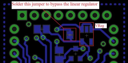
Ok. Let me explain the 3.3 linear regulator. I added this option to the board in case there is no pre-regulated 3.3v source, but it inherently contradicts the purpose of using a Bluetooth 4.0 module: extremely low power consumption. I tried to get a reading on the milliamps the HM-10 pulls, but my multi-meter only goes to the tenths (ma) and the module wouldn’t show at all, even during active use. And as many (all?) probably already know, the linear regulator is extremely inefficient. So, it’s much better to solder the jumper that bypasses the regulator and leave it un-populated. UPDATE: I’ve found info on power consumption:
- Sleep mode 400~800uA
- Search Mode for Master: 19.6mA
- Transmission (Slave or Master): 8.5mA.
4. Populate the breakout board.
A few notes on soldering the SMD pieces:
- DON’T BE SCARED. It’s really not that hard.
- There are three musts to SMD, at least from my perspective: a small iron tip, sharp pointed tweezers, thread-like solder (at least .022” solder wire).
- Other important soldering tools: A wet sponge and brass-ball will keep your fine soldering tip _fine. _Sponge the solder tip, then run it through the brass-ball after each component to prevent build-up.
- To speak blasphemy: Flux is ok, but I find the tweezers often take place of the flux.
- Practice using both hands during soldering. Tweezers in one and solder-iron in the other.
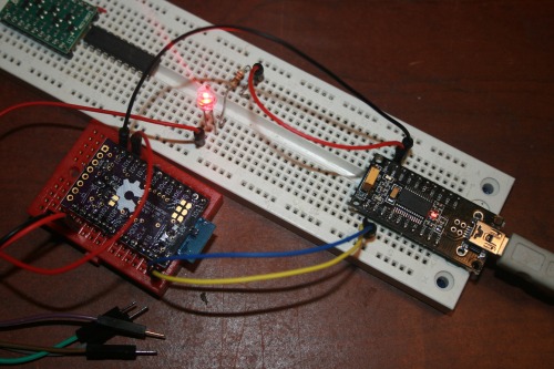
5. Wire it up to serial port.
So, this is the board I screwed up on. Basically, like a dumb-ass I was trying to regulate 3.3v with a voltage divider. Of course, I know better now. Still, given the HM-10 pulls fewer than 10ma, I’ll probably go back and run the math to see if as voltage-divider is, in fact, a feasible solution.
Anyway, the hookup is pretty simple.
- BT-3.3v <—> 3.3v
- BT-RX <—> FTDI-TX
- BT-TX <—> FTDI-RX
- BT-IO1 <–> LED <–> 220 Res. <–> GND
- BT-GND <—> FTDI GND
-
(For the 3.3v I used a regulator and tied my grounds).
- A few notes, the RX and TX lines are translated from 3.3v to 5v by way of a voltage divider and the BS1138. All other lines will die at >3.3v.
Now, as I’ve stated, I’m connecting two modules together, so you have to set one module as the slave.
I used RealTerm to access the HM-10s firmware via AT commands (full list in the manual).
HM-10 Setup Instructions
- Under the “Port” tab
- Baud: 9600
- Parity: None
- Data Bits: 8
- Stop Bits: 1
- Hardware Flow Control: RTS/CTS
- Software Flow Control: Receive–Yes, Transmit–Yes
- Under the “Echo Port” tab
- Echo On: Yes
- Monitor: Yes
Then, under the “Send” tab type in AT commands and hit “Send ASCII”:
- Send: AT
- Response: OK
Now, setup one unit as the slave (they default as master).
- Send: AT+ROLE1
- Response: OK+Role:Slave
That should be all we need to do to setup the connection. Now, whenever they power on they will automatically try to mate. You’ll know if they are connected if the LED goes from blinking to solid.
7. Wire the modules to the target devices.
- BT-3.3v <—> Arduino 3.3
- BT-RX <—> Arduino TX
- BT-TX <—> Arduino RX
- BT-IO1 <–> LED <–> 220 Res. <–> GND (or if you’ve soldered on the 0603s you can skip that connection).
Notice the mistakes routing my board? :(
It was salvageable though.
10. Turn on the devices and make sure the LEDs go solid.
(10a. Yell at me if it doesn’t work.)
11. If the LEDs go solid, then you have a serial connection between the devices. Have fun :)
Some things I’ve discovered:
- They have much better range than I would have thought. I’m getting around 30ft indoors. I’ve not tried them outside. For those of you who’ve read my developing post: Yes, having the copper planes underneath the antenna is what caused the range issue. They’ve got super range now :) UPDATE: I found info on range: 60 feet indoors, 300 feet line-of-sight.
- They connect much faster than older Bluetooth devices.
- Actively sending or receiving draws fewer than 10mAs :)
- I love these little guys over Xbees :)
Research Towards a Hub and Node network using the HM-10s:
11/18/2013
The Theory:
So, I’ve been working on putting an ATtiny 85 at the end of the HM-10’s serial line to allow for remote control of AT commands. It goes something like this:
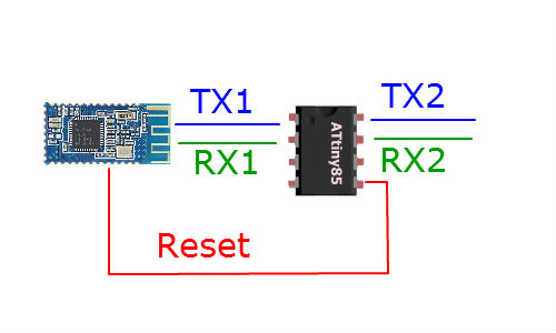
Using Software Serial to setup two serial lines. Basically, the ATtiny 85 acts as a filter on the serial line. If it is a regular message it passes from TX1 to TX2. But the code in the Tiny will be looking for serial data that begins with “AT+” and if it sees something, it will instead write that command to RX1.
Now, stick with me a minute.
The Master has a mode called Remote, which is setup with the command AT+MODE2. While in Remote mode the HM-10 will transmit serial data but also accept AT commands. Sadly, this seems to only work on the Master. So, we must have a different setup for the slaves.
In the case of the slaves we use the reset line. Each slave will have the ATtiny filter, but when it gets an “AT+” command in the serial data it will pull the reset line low. This resets the HM-10. We do this because the HM-10 has a command AT+IMME1 and this will put the HM-10 Slave into a mode where it wont automatically seek to pair. Instead, it will accept AT commands until given the command “AT+WORK” whch will send it into pairing/transmission mode.
Ok. Going back to our Slave setup. So, when we setup our HM-10/ATtiny combos as Slaves, we put them all in the mode where they don’t seek to pair until given the command AT+WORK. Of course, we program the ATtiny to send the HM-10 into pairing mode whenever it is turned on. Then, once it pairs with our Master we can send a serial message through the Master to the Slave with the string, “AT+RESET&AT+PIO11&AT+WORK” When the ATtiny gets this code it will pull the reset line low, putting the Slave back in AT mode. Then, the ATtiny connected to the slave will send the command AT+PIO11 which puts pin 1 on the HM-10 high. After, the ATtiny gives the command to the Slave to re-enter transmission mode. Voila.
Alright, so far, I’ve got all that coded and the hardware worked out–most everything above I can confirm works.
But, I’ve been skeptical as to whether or not the HM-10 will connect quick enough for a Master to have a seemingly seamless transmission between Slaves. I derived this skepticism from watching the blinking connection LED everytime I reset one of the HM-10s that was formerly paired. Then it hit me. They weren’t immediately reconnecting because the Slave still thought it was connected, therefore, the HM-10 firmware had not re-initialized pairing protocol. I tested it. And sure enough, if a Master and Slave are paired, one loses power, then the other will hang for 3 seconds before trying to pair again. But, if one loses power and the other one is reset at the same time, when they both power back on (<100ms) they will almost immediately pair.
Booyah!
So, all we have to do is setup a code where a Master connects to a node, tells it what it needs to, then tells it to reset itself,. Afterwards, the Master changes its own pairing pin, then resets itself, whenever the Master comes back up it should almost immediately connect to the new node.
And there we go. A viable Bluetooth 4.0 Star Network. I hope to have this fully tested before the Holidays.
11/23/13
(Warning: Lots of vehement expression towards datasheet-writers)
Ok. So here is what’ve I learned.
Alright, I’m beginning this article by saying; I love the HM-10. Excellent device. However! I want to beat the ever loving poo out of their datasheet writer. To begin, I’ve ordered several HM-10s from www.fasttech.com over the course of several months. And it never dawned on me they were upgrading the firmware quicker than I could buy them. This wouldn’t be too bad, but it’s like the HM-10 monster took a poo and the datasheets are the result: actual commands for listed firmware versions don’t match the datasheets, there is different information in the Chinese datasheets than the English, some AT commands have been merged without being stated. It’s just fubar.
So, some of the issues I’ve had trying to network the little devices I believe has come from firmware versions not playing nice.
For example, the HM-10 V303 has a command AT+IMME1 (0 to turn it off) for the Master only that keeps it in AT mode until given the command AT+WORK. I discovered that stupid-ass jnhuamao changed the firmware at some point (in the 4xx range) and this command merged with AT+START, which in my V303 datasheet is a command for something else. F’in poor translation.
Now, I have 2 boards with firmware V303 and 1 board with V502. I also have 2 modules that I bought later which more than likely have something greater than V502. I’m praying they are V508 or greater; at V508 they added the feature to upgrade the firmware through the serial line. ‘Bout damn time.
I can’t find the datasheets (in either language) for V502, but looking at the V508 I can see the AT+TYPE command now has three options. The V303 lists only two options for AT+TYPE. Yet, somehow, my V303 boards actually take this third option (AT+TYPE2). Bizarre.
Moving on from the firmware and datasheet mess: Using the ATtiny 85 does work, but to get the HM-10 to take the commands it requires:
- TinySerial.write(“AT+xxxxx”);
So, in theory, to get a HM-10 Master setup to only enter transmission mode when given a command, it goes something like this:
- TinySerial.write(“AT+RENEW”); //Reset to factory settings.
- TinySerial.write(“AT+ROLE0”); // Be the Master.
- TinySerial.write(“AT+IMME1”); // Don’t enter transmission mode until told.
- TinySerial.write(“AT+RESET”); // IMME takes effect after reset.
- TinySerial.write(“AT+”START”); // Ok, try to connect to something.
This resets it to factory settings, tells it not to connect until given the command, then it gives the command to start trying to connect.
Here’s example code I use on the ATtiny 85:
  /*
  This code has been modified for use on an ATtiny.
  Created by Matthew on June 11, 2013
  http://projectssfromtech.blogspot.com/

   This example code is in the public domain.

   */


  #include
  SoftwareSerial TinySerial(3, 4); // RX, TX
  SoftwareSerial TinySerial2(1, 2); // RX, TX

  String blah;
  int incomingByte = 0;

  void setup()
  {
    // Open serial communications and let us know we are connected
    TinySerial.begin(9600); //Serial line for the ATtiny85 to read/write from/to the HM-10.
    TinySerial.println("Tiny Serial Connected via SoftwareSerial Library");
    TinySerial2.begin(9600); //Serial line for the ATtiny85 to print to a serial port.
    TinySerial2.println("Tiny Serial Connected via SoftwareSerial Library");

    TinySerial.write("AT+RENEW"); // Reset all settings.
    delay(300);
    TinySerial.write("AT+ROLE0"); // Slave mode ("AT+ROLE1" is slave and "AT+ROLE0" is master)
    delay(300);
    //TinySerial.write("AT+PASS001111"); // "AT+PASS001111" sets the password.
    //delay(300);
    //The work mode only works for the Master HM-10.
    TinySerial.write("AT+MODE2"); //"AT+MODE0" = Transmission Mode, "AT+MODE1" = Remote Control Mode, "AT+MODE2" = Modes 0 + 1.
    delay(300);
    TinySerial.write("AT+IMME1"); // Don't enter transmission mode until told. ("AT+IMME0" is wait until "AT+START" to work. "AT+WORK1" is connect right away.).
    delay(300);
    TinySerial.write("AT+START"); // Ok, go ahead and enter. BULLSHIT! Apparently "AT+WORK" is not what we use, it's "AT+START"
    delay(300);

  }

  void loop()
  {

  }
Ok. I also learned a little more about PIN command. To begin, “AT+PASS000001” will set the PIN, not “AT+PIN000001”. Of course, it must be a 6 digit number, so, fill the others with zeros. Now, depending on the firmware version there are 3 different settings for PIN pairing, all set by AT+TYPEx
- AT+TYPE0 – this is supposed to be “Connect without password mode”
- AT+TYPE1 – “Simple pairing” (no explaination).
- AT+TYPE2 – “Requires PIN for pairing”
Alright. So, this was the key to my switching between modules. I thought I would set a unique PIN for each slave and the ATtiny 85 connected to my Master would switch the PIN on my Master depending on which node I wanted to connect. Well, this feature is broken. I played with it for several hours and no matter how I set the PIN or TYPE settings, the modules would pair even without the correct pin. I could find no answer for this behavior. Until, I read through the Chinese version of the datasheet and came across this gem.
- “IMPORTANT: V515 previous versions, the directive no practical effect, after setting causes not connect, please do not use.”
Of course, this is a Google translation. But I’m pretty sure I read that, “This feature on versions under V515 does not work.”
And that’s where I am at the moment. I wanted to make sure I wrote some of this stuff down in case others were running into problems. My next projects will be writing to jnhuamao and get some questions answered (e.g., “Any way to get upgrade the firmware on versions less than V508 so I’m not left with 5 unsecure HM-10s; maybe through the SPI interface?).