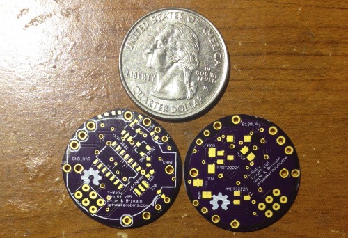
I printed a body and added BLE. I’ll explain tomorrow after I get some rest, but the BLE was to allow me to test directed locomotion. I’ve also done some feature testing (load-sharing, charging circuit, “hunger” ADC), the board is actually a good design. Works well.
The BLE is the HM-11, itty-bitty BLE.
My goal is to test the physical and feature designs with the ATtiny84, and when Mr. Bdk6 releases his toolchain for the LPC1114, switch it as the controlling chip.
This is my version of Yahmez’ Baby Bot, the ATtiny84 Y-Baby (YB84). There are few differences from Yahmez’ version.
This version uses an ATtiny84.
It uses a LIR2032.
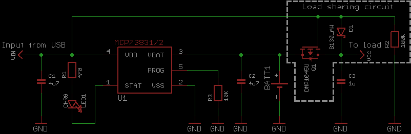
It has a charge circuit built in, using the MCP73831. This circuit has load-sharing capability so the baby can “feed” without sleeping.
The YB84 has two LED indicators.
One pin on the YB84 monitors the battery voltage, so it can tell how “hungry” it is.
This version came about because Yahmez’ Baby Bots were so damn cool I had to copy them. Here’s the node where I asked permission and added design notes. Also, I’ve wanted to make a small, cheap, small robot to couple with my Overlord projects in hope to develop an electronic lab-rat.
Note, I’ve not included the IR receiver or IR transmitters in the BOM. I’ve not tested the circuit yet, or sourced cheap parts. But I’m shooting to keep them under $10.
YB84 BOM Total: $7.70
YB84 v_05
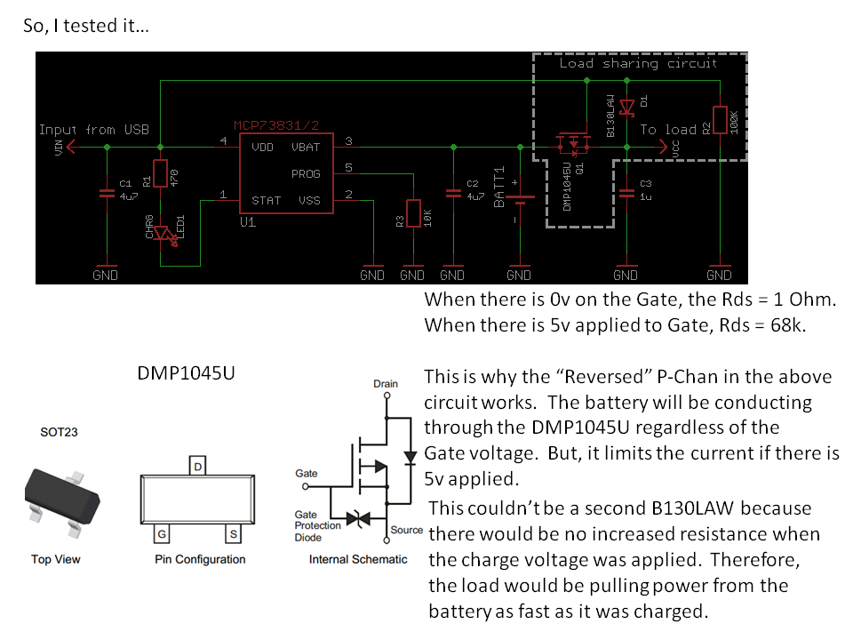
Really, there wasn’t much to developing this little guy, Yahmez had done all the work. I simply selected an Atmel uC that I felt was cheap enough and provided enough pins to accomplish what I wanted to do with the little guy. The one problem I had was with the load-sharing circuit I tried to copy from Zak Kemble.
When I went to layout the load-circuit my mind got locked on the old thought, “MOSFET diodes go against the current.” This caused me to lay the DMP1045U down backwards, which essentially shorts the battery.
This took me a bit to figure out. I apparently wasn’t the only one that made the mistake, as a comment on Zak’s blog had a fellow asking my questions for me. In the end, I got the circuit sorted out and now the little guy works as intended.
That’s about it for now. I still have lots of testing to do on the little guy.
Motor placement for correct movements.
Leg angling for correct gait.
IR-RX circuit.
IR-TX circuit.
Currently, I have a pogo-pin programming header. But it is imperative to accomplish my goals for this little guy to make him programmable via IR. This should allow me to program a swarm of these little guys without manual interaction. I know the Kilotbot projects modified the Arduino code to do this very thing. My ideal setup is to add a mobile hanging over a swarm of these guys. On this mobile would be: IR-TX, IR-RX, and a camera. The camera would be using Overlord to track these guys and the IR to communicate with them in mass.
As always, thoughts, opinions, and critiques I welcome :)
After I was able to get my motors moving using the SN754410 I became a little obessessed with understanding AVR PWM architecture. There are several tutorials that helped me a lot:
In the end, I ripped maxEmbedded code and got my PB3 LED working in about 10 minutes. Then, I spent the next three evenings reading trying to figure out what maxEmbedded’s code was doing.
Really, it was the register and bit names that were tripping me up. Each had names like, “TCCROA1” and “OCR0A”, and so forth. Each is an initialism. This was a problem for me, I was soon lost in a jungle of intialisms, which represented abstract concepts, such as other intialisms. I felt as if I were bumbling through a George MacDonald dissertation on an orc language:
NOTE: Dear reader, I apologize if that video confused you more. Again, this is a journal so to help me remember what I learn. And I find adding a story to ridicules abstractions is necessary for me.
Alright, now that I had a little story in my head to handle the intialisms learning PWM on the AVR flowed a little easier.
Here is my reference list:
1. TCCR = Timer/Counter Control Register.
On the ATtiny1634 there are 4 control registers. One is 8-bit and the other is 16-bit. Though, this journal will stick with the Arduino standard, meaning, I’ll use my 16-bit as an 8-bit. Here are the four Timer/Counter Control Register names:
TCCROA (8-bit)
TCCROB (8-bit)
TCCR1A (16-bit)
TCCR1B (16-bit)
TCCROA (8-bit timer) and TCCROB (16-bit timer) control the PWM functions of pins.
TCCROA/B control pins PA5 and PA6.
TCCR1A/B control pins PC0 and PB3.
2. COM = Compare Output Mode
There are four bits per TCCR register that control the compare output of each pin. This is where the magic happens. If a pin is setup in compare output mode, it will only go high when the counter is equal to or higher than a number you provide. For instance,
Is timer greater than 100? Then go high.
This is the essence of PWM. You provide a number, in our case a number between 0-255 since it is an 8-bit counter, and if the timer is equal to or greater than your number, the pin will be HIGH. Then, the timer will continue to count up and will reset to 0 after 255 is reached. Mind you, the comparison is made every tick of the counter, so when it resets to 0 the comparison will be made and the pin will go LOW ago. Voila!
There are four COM bits in each TCCR register, two control the output of one pin.
Found in TCCR0A:
COM0A0 and COM0A0 control pin PC0.
COM0B0 and COM0B0 control pin PA5.
Found in TCCR1A:
COM1A0 and COM1A1 control pin PB3.
COM1B0 and COM1B1 control pin PA6.
Now, switching these bits can create many different types of output. But I stuck with Arduino standard.
3. WGM = Wave Form Generation (for 8-bit)
There are 3 bits that control the type of PWM we end up with. There are all sorts of wave-forms, but the main three are:
Phase Correct
CTC
Fast PWM
(Here is an Arduino article that explains them a bit.)
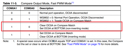
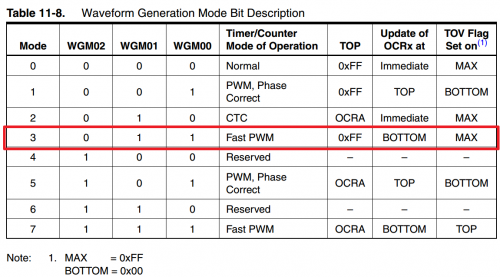
The one I’ll invoke is Fast PWM,
We select this by setting WGM00 and WGM01 bits.
4. How to set the TCCR registers.
So, setting things up, the code will look something like this,
// Demonstration of PWM on an ATtiny1634.// C. Thomas Brittain#define F_CPU 8000000 // AVR clock frequency in Hz, used by util/delay.h
#include <avr/io.h>
#include <util/delay.h>
//Initialize PWMvoidpwm_init(){//This is the first PWM register, TCNT0. It is 8 bit. Both PIN PA5 and PA6 are set to clear on compare,//then set at bottom; this makes them non-inverting. The WGM bits are set to for "Fast PWM MODE"//and this clears at the top, "0x00FF."TCCR0A=0b10100011;// WORKS FOR OC0A, OC0BTCCR0B=0b00000001;// WORKS FOR OC0A, OC0B//This is the second PWM register;TCNT1. It is 8 bit. Both PIN PB3 and PC0 are set to clear on compare,//then set at bottom; this makes them non-inverting. The WGM bits are set to for "Fast PWM MODE"//and this clears at the top, "0x00FF."TCCR1A=0b10100001;//WORKS FOR OC1A, OC1BTCCR1B=0b00001001;//WORKS FOR OC1A, OC1B//This sets the PWM pins as outputs.DDRB|=(1<<PINB3);DDRA|=(1<<PINA5);DDRA|=(1<<PINA6);DDRC|=(1<<PINC0);}
I left the assignment of the TCCR registers in a binary format. This was just easier for me, but you could as easily use bitwise operations, e.g.,
TCCR1A|=(1<<COM1A1)|(1<<WGM01)
You notice we set the COM0A1 or COM1A1 bits, but later I’ll change this so they are not set at initialization. I found if you connect the pins to the timers at the beginning, then they’ll constantly have a nominal voltage on them. This is made clearer if you have an LED on the pin. Therefore, unless you set the COM0A1 and COM1A1 bits low then the LED will never fully turn off.
Also, we have to set the data direction registers for the PWM pins to outputs.
Now, that the initialization is done, let’s look at the code I used to demonstrate PWM on the ATtiny1634.
intmain(){uint8_tbrightness;// initialize timer0 in PWM modepwm_init();//Setup several duty-cycle counters to show differential PWM channels.uint8_tbrightness2=0;uint8_tbrightness3=0;uint8_tbrightness4=0;//Let's only do this 3 times before turning PWM off.for(intcounterB=0;counterB<2;++counterB){//The main duty PWM cycle counter will also be our loop counter. (0-255)for(brightness=255;brightness>0;--brightness){// set the brightness as duty cyclebrightness2=brightness2+1;brightness3=brightness3+2;brightness4=brightness4+10;OCR0A=brightness;// PCO0OCR0B=brightness2;// PA5OCR1A=brightness3;// PB3OCR1B=brightness4;// PA6//Delay to make changes visible._delay_ms(40);}//After 3 loops clear the PWM channels by setting COM0A1 and COM0B1 bits low.//If this is not done then there will be a nominal voltage on these pins due to//the internal pull-ups setting them as outputs.TCCR0A=0b00000011;// WORKS FOR OC0A, OC0BTCCR1A=0b00000011;// WORKS FOR OC0A, OC0B}}
You’ll notice this is a modified “Fade” sketch from the Arduino world.
The above code provided this output,
How the magic happens in AVR is around the output comparison registers,
OCR0A – controls PC0
OCR0B – controls PA5
OCR1A – controls PB3
OCR1B – controls PA6
Basically, the OCR registers flip the pin HIGH or LOW (as setup by the TCCR) based upon the number you assign to it. If you assign OCR0A a value you of 144, it’ll be LOW (0v) for 144 clock cycles (TCNT) and HIGH (5v) for 111 clock cycles. This gives us our PWM. Booyah!
OCROA = 127;
This sets PC0 to approximately 2.5v. (127/255bit * 5v = ~2.5v)
OCR1A = 255;
This sets PB3 to 5v. (255/255bit * 5v = 5v)
Ok, here’s the tricky one,
OCR0A = 0;
This should set PC0 to 0v, but that’s not the case. When we set the COM registers (COM0A1, etc.) there are internal pull-up resistors connected to the corsponding pin. This results in a constant nominal voltage unless the COM register is set low again.
This can be done using the XOR operator on the TCCR register,
TCCRO ^= (1«COM0A0)
This should set the PC0 pin to 0v.
It’s really that simple…well, unless you want to mess with the type of PWM you are creating. Ugh.
5. ATtiny1634 analogWrite.h
After I figured out how to use PWM on the ATtiny1634, I started thinking how nice it would be to re-create the Arduino library for it.
Being able to write,
analogWrite(pin, strength)
had a lot of appeal to me.
I played with it a bit and ended up with the following,
#ifndef analogWrite1634
#define analogWrite1634
#include <avr/io.h>
#include <util/delay.h>
voidanalogWrite(intPWM_PinSelect,intduty);// initialize PWMvoidpwm_init(){//Define PWM pins.#define PWM_PC0 1
#define PWM_PA5 2
#define PWM_PA6 3
#define PWM_PB3 4
//This is the first PWM register, TCNT0. It is 8 bit. Both PIN PA5 and PA6 are set to clear on compare,//then set at bottom; this makes them non-inverting. The WGM bits are set to for "Fast PWM MODE"//and this clears at the top, "0x00FF."TCCR0A=0b00000011;// WORKS FOR OC0A, OC0BTCCR0B=0b00000001;// WORKS FOR OC0A, OC0B//This is the second PWM register;TCNT1. It is 8 bit. Both PIN PB3 and PC0 are set to clear on compare,//then set at bottom; this makes them non-inverting. The WGM bits are set to for "Fast PWM MODE"//and this clears at the top, "0x00FF."TCCR1A=0b00000001;//WORKS FOR OC1A, OC1BTCCR1B=0b00001001;//WORKS FOR OC1A, OC1B//This sets the PWM pins as outputs.DDRB|=(1<<PINB3);DDRA|=(1<<PINA5);DDRA|=(1<<PINA6);DDRC|=(1<<PINC0);}voidanalogWrite(intPWM_PinSelect,intduty){//Make sure we were passed a number in-range.if(duty>255)duty=255;if(duty<1)duty=0;//Sets PWM for PC0if(PWM_PinSelect==1){if(duty>0){TCCR0A|=(1<<COM0A1);OCR0A=duty;}else{TCCR0A^=(1<<COM0A1);}}//Sets PWM for PA5if(PWM_PinSelect==2){if(duty>0){TCCR0A|=(1<<COM0B1);OCR0B=duty;}else{TCCR0A^=(1<<COM0B1);}}//Sets PWM for PA6if(PWM_PinSelect==3){if(duty>0){TCCR1A|=(1<<COM1B1);OCR1B=duty;}else{TCCR1A^=(1<<COM1B1);}}//Sets PWM for PB3if(PWM_PinSelect==4){if(duty>0){TCCR1A|=(1<<COM1A1);OCR1A=duty;}else{TCCR1A^=(1<<COM1A1);}}}#endif
A synopsis of the library,
Lines 1-2 and 90 make sure the library is only included once.
Lines 13-16 define the ATtiny1634 pins.
18-28 setup the TCCR registers (notice, the pins start out off to prevent nominal voltage).
41-42 makes sure our PWM value is in range.
46-85 control the PWM on each pin, with an else statement to gives us a true zero voltage in the case a PWM value of 0 is passed to the function.
I saved this as 1634analogWrite.h and then wrote a sketch to use
// program to change brightness of an LED// demonstration of PWM//void Tiny1634_PWM(int PWM_PinSelect, int duty);#define F_CPU 8000000 // AVR clock frequency in Hz, used by util/delay.h
#include <avr/io.h>
#include <util/delay.h>
#include "1634analogWrite.h"
intmain(){uint8_tbrightness;// initialize timer0 in PWM modepwm_init();intbrightness2=255;intbrightness3=255;intbrightness4=255;// run foreverwhile(1){for(brightness=255;brightness>-1;--brightness){analogWrite(PWM_PC0,brightness);analogWrite(PWM_PB3,brightness2);analogWrite(PWM_PA5,brightness3);analogWrite(PWM_PA6,brightness4);_delay_ms(10);brightness2=brightness2-5;brightness3=brightness3-10;brightness4=brightness4-15;if(brightness==0){_delay_ms(1000);}if(brightness2<0)brightness2=255;if(brightness3<0)brightness3=255;if(brightness4<0)brightness4=255;}}}
Ok. I’ll revisit this probably with a complete H-Bridge control library.
As always, please feel free to correct my f’ups.:)
Here are some random notes on working with the HM-10.
Working RX/TX LEDs
How upgrade the HM-10
Pseudo Star-Networking HM-10s
Working RX/TX LEDs
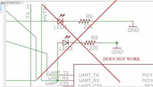
I spent some time trying to find a way to create RX/TX traffic LEDs for the HM-10 breakout. This might be easy for some, but it was a real thinker for me. The HM-10 is TTL, which as it was explained me, means that the line is high while idling and low to represent data. The problem here is the typical LED setup doesn’t work. Sadly, this is the setup I used in two of my fabricated boards.
Well, this stupid mistake has been staring me in the face. Especially since a few guys ordered my board and mentioned politely, “It only flashes when large amounts of data go through.”
After asking around I was told the best way to approach this problem was to use a PNP transistor. The guys at LMR pretty much gave me the solution here. The people here are brilliant. (Please don’t tell them I’m not, I want to hang with the cool-kids for a bit before they find out my mom still dresses me.)
But while LMR was helping me I found Sparkfun’s solution to the problem on one of their Xbee Explorer boards. In essence, the LEDs are wired from in between 3.3v and the TX/RX lines, this allows them to act as sinks whenever the data is coming through. As long as the LED is a green, blue or other with a 3.1v drop, then the voltage being sunk doesn’t interfere with the data.
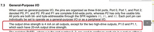
Of course, this is risky. The CC2540 is a nifty chip, but it isn’t meant to be a high-current uC. I dug through the datasheet to see what the current sink rating of the RX/TX pins (2 & 3) were. Well…it’s not in the datasheet! But then I came across this post.
Well, there we go. So, I breadboarded a circuit and found it worked. But I was only brave enough to use a 1k resistor.
Eventually Brassfly helped me work through the math,
“Given that the voltage drop across the forward biased junction of a red LED is about 2 Vdc (we will call that Vf) the total current through the LED/Resistor is equal to Vsupply-Vf/R, or in this case 3.3V-2V/1000=.0013A=1.3mA….If they are bright enough then don’t worry about it. If not, you might then consider using a 470 ohm resistor (2.7mA) or even 330 ohm resistor (3.9mA).”
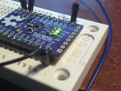
So, I made up a fresh version of the HM-10 breakout board (v.9.9) with this LED setup. I wired it up. And, it seems to be working.
Again, can’t use yellow or red LEDs on the RX/TX lines, since they do not create a high-enough voltage drop to signal the CC2540 low).
How upgrade the HM-10
(NOTE: You can only upgrade versions 507 or later, according to Jnhuamoa)
1. Visit the HM-10 website and learn all about the HM-10 upgrade process.
2. Download the lastest firmware version file. (Make sure your HM-10 is a CC2540, if it’s CC2541 use that file).
3. Before we proceed, here’s my bitchy disclaimer. Re-read the instructions and b_eware all ye who try to upload firmware and don’t blame me for problems, like the death of your HM-10 :P_
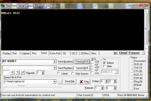
4. Open Realterm (or your preferred serial terminal).
5. Wire your HM-10’s serial connection as described in my earlier post.
6. You are about to cross the point of no return. Open a serial connection to the HM-10 and if you are prepared for the worst, type: “AT+SBLUP” and the module should reply, “SBLUP+OK.” Congratulations, you’ve bricked your HM-10–well, at least until the upgrade process is complete.
7. Now, CLOSE YOUR SERIAL CONNECTION in Realterm. Yes, I forgot to close the connection myself and was pissed because I thought I had bricked my HM-10 when I tried the next step. I’m a hack, hacking with a hacksaw.
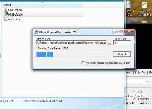
8. Unzip the “HMSoft-10-2540-V522.zip” (or the latest version, respectively) into a folder. There should be several files in the folder, open HMSoft.exe
9. Now, click on the ellipsis and select “HMSoft.bin” file. Then, type the number of your com port. You don’t need to include anything but the number (e.g., COM34 becomes 34).
10. Pray (for the HM-10 this works best if to Nyarlathotep).
11. Click “Load Image.” The upload process should start pretty quick and should take approximately a minute and a half to complete. Do not remove power or screw with the wiring until you see the following:
12. Click “Ok” and open Realterm. Bring up a serial connection and type: “AT+VERS?” It should respond, “HMSoft v521.” That’s not a typo, even though we uploaded the V522 version it responds saying it is V521? You got me. But it works ok :)
Pseudo Star-Networking HM-10s
Setup up at least three units.
Unit #1 (“Master”)
AT+ROLE2
AT+IMME1
AT+CONxxxSLAVE#1xxxx
Unit #2 (Slave #A)
AT+ADDR? Write the address down. Mine replied, “OK+ADDR:883314DD8015”
AT+MODE1
Unit #3 (Slave #B)
AT+ADDR? Write the address down.Mine replied, “OK+ADDR:883314DD8016”
AT+MODE1
Oh, one more bit. You need to wire pin 4 on the Arduino to the HM-10 Master’s reset line. Since there really isn’t anyway to reset the slave and the master at the same time. This gets us around the timeout for both, slave and master.
RESET<—-1k Resistor—–>D4 on Arduino
Then use the following code, changing your addresses respectively.
// Crap code for HM-10 pseudo-Networking// By the crappy code Thomas Brittain, aka, Ladvien.StringinputString="";// a string to hold incoming databooleanstringComplete=false;// whether the string is completeString inputString = ""; // a string to hold incoming datafloattime;floatoldTime;voidsetup(){// initialize serial:Serial.begin(9600);pinMode(4,OUTPUT);digitalWrite(4,LOW);}voidHM10Reset(){Serial.print("AT+RESET");delay(220);digitalWrite(4,HIGH);delay(100);digitalWrite(4,LOW);delay(150);}voidloop(){// print the string when a newline arrives:Serial.write("AT+CON883314DD8016");delay(150);Serial.print("From first node! Seconds ago last here: ");time=millis();Serial.println((time-oldTime)/1000);oldTime=millis();delay(250);HM10Reset();Serial.write("AT+CON883314DD8015");delay(150);Serial.println("From second node!");delay(150);HM10Reset();}voidserialEvent(){while(Serial.available()){// get the new byte:charinChar=(char)Serial.read();// add it to the inputString:delay(50);inputString+=inChar;stringComplete=true;}}
Not going to lie. I’m pretty dissapointed with how complicated the firmware makes it to switch between nodes. Although, I’ve only begun to play with firmware versions greater than V303.
I couldn’t do much better than about 2.84 seconds switching between nodes. This simply wont do for me. And, of course, this rate goes up with more nodes. So, a swarm of little robots controlled this way would be unmanagable.
I tried tweaking the timing of everything in the code. The HM-10 wasn’t having it. If I lowered the delay following an AT command it, the command wouldn’t take. This would often cause the nodes to become stuck (waiting for timeout, still connected, etc.) Also, the hardware reset on the HM-10 is said to be 100ms, but I’m finding it unhappy with much less than 250ms.
Anyway, if anyone else wants to carry the banner my suggestion is uping the buad rate and sticking with hardware resets, like in my ATtiny Bitsy Spider board.
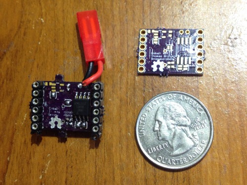
Awhile back Sparkfun posted a new product, their MiniMoto breakout board. It breaks out the DRV8830 IC, which is a serially controlled (I2C) H-Bridge. I thought the chip was nifty. A few problems though,
Sparkfun’s breakout was 25x25mm for one bridge. If I added another and then an Arduino Pro Mini it’d lose smallness.
It’s $9.95
It’s not on a purple board :)
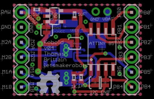
So, I set out to make a robot controller with it that was smaller than a Sparkfun breakout. What I ended up with is a little bitch I refer to a Kobold.
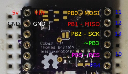
The board is pretty straightforward. It has an ATtiny 85 that acts as an I2C Master using the SoftI2CMaster library. This allows the Tiny 85 to control two motors using only two pins, leaving three for your pleasure.
My end goal will be to build a shield for it and hook up a HM-10 to make it a little wireless tethered bot. This would bring me down to one pin, which I’m sure will be some sort of range finder or feeling sensor.
I’m currently working on a second iteration to correct some problems. I’ll also add a few features, like my pogo-pin programming interface. The shield I have designed for it will also include a charging circuit and probably a SMD step-up circuit that should convert a LiPo to a nice 5v.
Anyway, work in progress…just thought I’d share.
If anyone is interested in this board, please wait a few iterations. I get worried I’m making blue-smoke with someone else’s money. :)
Here is the code running in the video:
//Sample Code for the Kobold Board.#define NO_INTERRUPT 1
#define I2C_TIMEOUT 100
#define SDA_PORT PORTB
#define SDA_PIN 4
#define SCL_PORT PORTB
#define SCL_PIN 3
#include <SoftI2CMaster.h>
#include <avr/io.h>
voidCPUSlowDown(intfac){// slow down processor by a facCLKPR=_BV(CLKPCE);CLKPR=_BV(CLKPS1)|_BV(CLKPS0);}booleanwriteSpeed(byteaddr,intspeedx){//This should clear the fault register.byteregValue=0x08;//Clear the fault status, in case there is one.if(!i2c_start(addr|I2C_WRITE)){returnfalse;}if(!i2c_write(0x01)){//0x01 = We want to write.returnfalse;}if(!i2c_write(regValue)){//Write the clear bye for fault register.returnfalse;}i2c_stop();//Stop transmission.//Let's convert the integer given us into a byte.regValue=(byte)abs(speedx);//Convert 0-63 to byte value to set speed.if(regValue>63)regValue=63;// Cap the value at 63.regValue=regValue<<2;// Left shift to make room for bits 1:0if(speedx<0)regValue|=0x01;// Set bits 1:0 based on sign of input.elseregValue|=0x02;//A negative number for reverse and positive for forward.//Now, let's move this sucker.//Sets the i2c slave addressif(!i2c_start(addr|I2C_WRITE)){returnfalse;}//0x00 = We want to write something.if(!i2c_write(0x00)){returnfalse;}//Writes the byte which had been converted from an integer that was passed this function. Annnnd! The motor moves!if(!i2c_write(regValue)){returnfalse;}i2c_stop();returntrue;}booleanwriteStop(byteaddr){if(!i2c_start(addr|I2C_WRITE)){returnfalse;}if(!i2c_write(0x00)){returnfalse;}if(!i2c_write(0x00)){returnfalse;}i2c_stop();returntrue;}//------------------------------------------------------------------------------voidsetup(void){#if I2C_CPUFREQ == (F_CPU/8)
CPUSlowDown();#endif
}voidloop(void){for(inti=0;i<=3;i++){delay(100);if(!writeSpeed(0xC0,10));if(!writeSpeed(0xCE,10));delay(1000);if(!writeStop(0xC0));if(!writeStop(0xCE));delay(1000);if(!writeSpeed(0xC0,-10));if(!writeSpeed(0xCE,-10));delay(1000);if(!writeStop(0xC0));if(!writeStop(0xCE));delay(100);}for(inti=0;i<=3;i++){delay(100);if(!writeSpeed(0xC0,14));if(!writeSpeed(0xCE,34));delay(1000);if(!writeStop(0xC0));if(!writeStop(0xCE));delay(1000);if(!writeSpeed(0xC0,-14));if(!writeSpeed(0xCE,-34));delay(1000);if(!writeStop(0xC0));if(!writeStop(0xCE));delay(100);}}


