
This is a continuation of my Robot Metallurgy 101 – AVR Lesson Journal
UPDATE: Now with UART(ish)! (3/2/2014)
I thought I would journal my work as I begin to venture from the comfortable playground of Arduino C and IDE.
I’ve tried a few other IDEs and C++ to work with different chips. But each time I realize I don’t know enough about C/C++, tool-chains, and workspaces to make a robot with them.
Bdk6 gave me an LCP1114 and I was able to get a blink program to run on it, but it was from a .bin file that someone else compiled, I simply uploaded it. I tried to work through two walkthroughs to get a programming environment setup (mbed and LPC1114). Bust on both.
I spent some time Googling, trying to find out what I was doing wrong. I came to the conclusion there was not enough information for an ignorant like me to figure out how to set up the workspace; the LPC1114 is an intermediate chip and I’m a beginner.
I decided to pull up tutorials on AVR programming. I knew there was an entire community around the Atmel chips, a community besides the Arduino community, a bare-metal community. I figured that would be the “beginner” environment to work in, since there would be enough documentation for me to learn
So, that brings us to my journal. I’ve not written this out to impress anyone. I simply find I learn better if I force myself to document what I’m doing. It encourages me to understand the information, since I have to explain it to someone else. Learning by verbal-processing. That being said, I invite criticism. Anything I’ve written that is incorrect, feel free to yell at me; it’ll learn me. Also, a lot of this has been written; I know I’m not being original. I’m also not delusional in believing I explain it better, but I do plan on making this journal flow towards how AVR programming can help me build better robots. Ok. Disclaimer done.
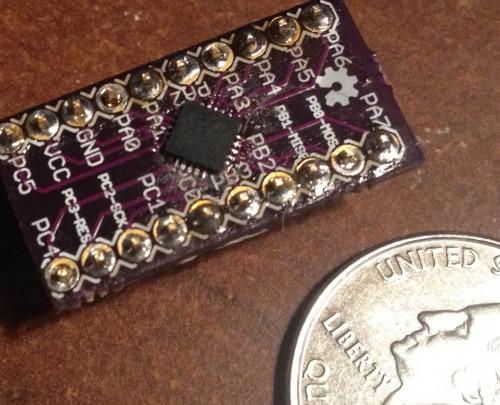
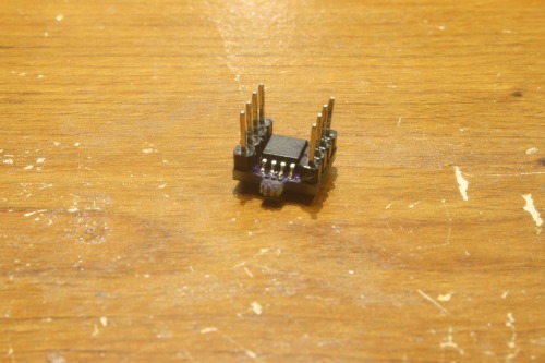
I ordered a few samples of the ATtiny1634.
A long time ago I bought an AVR ISP MKII to program these boards
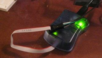
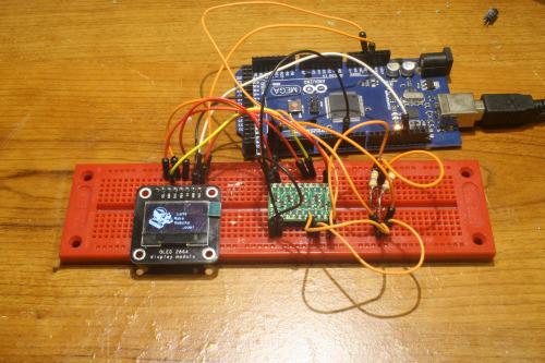
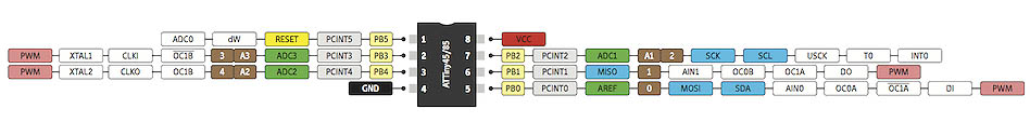
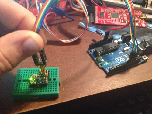
I wired up the 1634 and the ISP like so,
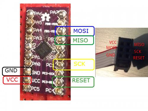
What do you mean the silk-screen is mislabeled…shh.
After I got the pinout all figured out, I downloaded Atmel Studio 6.1. I know there are many different opinions about what IDE to use, and a lot of them seem to favor a text editor and AVRDude, for a change I wanted to go with a commercial IDE. Also, it seems like a lot of those in the AVRFreaks group actually like Atmel Studio.
It’s pretty easy to set up. You install it. Plug in your AVR ISP MKII. Then, File–>New Project. Select “GCC C Executable Project” and name your project. Hit “Ok.” Atmel Studio will bring up a list of supported chips. I scrolled down until I found my chip, “ATtiny1634.” You’ll notice the datasheet and supported programmers are to the side.
Alright, so, here I was. IDE all set up…um, now what do I do?
I began to Google until I found an AVR Tutorial Series that looked like it would bring me from the basics, well, up to Serial communication. Really, I figure if I could learn the following I could build whatever I wanted out of it:
Luckily, I found the series put together by Newbie Hack’s series.
So, I decided I would try to walk through all of his tutorials and see if I could apply them to the ATtiny1634. NOTE: The author of this series appears to be Patrick Hood-Daniel, a fellow Texan (don’t hold that against us :P).
1. Blinkin LED
Newbie Hack’s MCU First Program.
I started Newbie Hack’s AVR Series after he had his programmer setup, his “First Program.” The uC’s version of the “hello world,” the LED blink. In Arduino I’d accomplish this like so,
int led = 13;

void setup() {
  pinMode(led, OUTPUT);
}

void loop() {
  digitalWrite(led, HIGH);   // turn the LED on (HIGH is the voltage level)
  delay(1000);               // wait for a second
  digitalWrite(led, LOW);    // turn the LED off by making the voltage LOW
  delay(1000);               // wait for a second
}
I got Newbie Hack’s code going within 3 minutes
I looked down at my breakout board, I had some “PBx” pins, so I figured I had a Port B. I located pin PB0 (the the pin marked “1” in the above image) and I threw my LED and resistor on it.
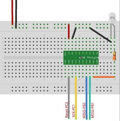
I uploaded the program and got this:
But the purpose of this journal is to understand what I’m doing, not just copy it. So, the following is an explanation to myself, in case I forget stuff.
What’s Going on in the Blinkin LED Code
Atmel chips are amazing. They are versatile little uCs and the way this versatility is utilized from programming is by changing bits within a byte. For example, a pin can work as either a INPUT or OUPUT, but how does the chip know which one? You change the Digital Direction Registry (DDR) Bit of the pin. The DDR bit is a little switch that can be flipped either on or off through programming. When it is off (0) the pin acts as an INPUT, when it is set on, it acts an OUTPUT.
Now, Atmel chips are divided into ports, and thee ports have 8 pins (or less). This allows one byte to control alot of the functions of one port.
Newbie Hacks (NB) does a great job of explaining this. He even draws out a picture;I like pictures.
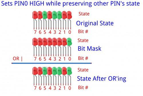
I like to think in images, so I see each bit as an LED. It makes sense, an LED has two-states ON/OFF; a bit has two states 0 or 1. So, a byte for me is 8 LEDs numbered 0-7.
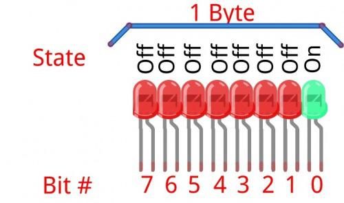
The above image could represent the following code:
DDRB = 0B00000001;
The Atmel chips have different ports, which usually have an array of pins. So, the DDR stands for digital direction registry of port B. Then, we assign a state to every pin on port B (PB0-PB7) by setting a bit to either 0 or 1. So, according to the image and our code, we are setting ports B1-7 as INPUTS (0 = INPUT) and PB0 as an OUTPUT.
But don’t be confused, the LED we have connected isn’t turned on yet. The voltage on PB0 still equals 0. But, we could now change the voltage from 0 to 5. We do this by changing another registry. The port state registry, PORTB.
PORTB = 0B00000001;
Actually sets pin 0 (PB0) on port B to 5 volts. The other pins are still set as inputs, so you can’t change the voltage.
That simple folks? Well, we also have to insert a delay. Delay’s are really just telling the uC how many cycles to do nothing. There is some math involved that divides the clock speed to get the exact time delay you would like in finite-ish numbers. This math is locked away as a function in the <util/delay.h> file. So, for our sake, it is a simple matter of adding:
_delay_ms(500);
This tells our Tiny to sit idle for half a second, then continue. Also, there is a _delay_us() function that will delay microseconds.
Ok. Here are my study-notes
Note #1: Adjusting the Clock Fuse.
I did have one modification I had to make to NH’s program. He uploads his program using AVRDude. Atmel Studio actually has libraries to specific to the Tiny1634, these are included when you setup your project. One of these libraries require you tell the program how fast the CPU is going to be running. The ATtiny’s have an internal 8mhz oscillator, but there is a Atmel fuse that is burned at the factory to divide 8mhz by 8, giving you a run speed of 1mhz. I wanted to be working with my 1634 at the full 8mhz.
So, I went to Tools—>Device Programming. You then have to select your “Tool,” for me the AVR ISP MKII; your device, ATtiny1634 for me; interface, ISP. Then click “Apply.” Now, under “Device Signature” click “Read.” This should bring up the Device Programmer window. Now, make sure you have your programmer wired to your chip correctly and you have a stable connection (might throw a .1uF radial capacitor between VCC and GND on the Tiny1634). Click on the “Fuses” tab.
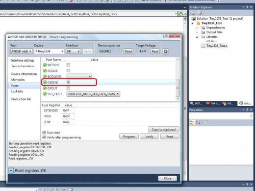
Uncheck the “CKDIV8.” It is the fuse that does exactly what it says, divides the clock by 8, reducing the chip from 8mhz to 1mhz. Don’t change any other fuses at this time. Hit the “Program” button. This will set the fuse. If all goes well we didn’t brick your chip.
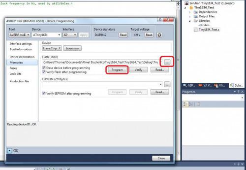
While we are under the device programming window, click on the “Memories” tab. This is where you will actually upload your compiled program onto the chip. Here, if you click on the ellipsis you can select the code you would like to upload. This ends in “.elf” (unless you are using a chip besides an Tiny, then it’ll end in .troll, hehe). So, select your code and then hit “Program.”
Now, Atmel Studio is setup to automatically program your code using the last selected devices whenever you hit “F5.” Sadly, I found this rarely worked properly. But I’m betting it’s because I have no decoupling capacitor–yes, I confirmed this. I put a 1uF radial capacitor between VCC and GND, now the “F5” programming works as expected. I’ve no idea. Seems to work if I manually program it though. Shrug.
Ok. Now we have our Tiny running at 8mhz, we will need to adjust this in our code.
#define F_CPU 8000000 // AVR clock frequency in Hz, used by util/delay.h</pre>
Here we are telling the program our chip is running at 8mhz (8,000,000 hertz).
After this, I uploaded the code and it ran just as I had hoped. The LED would be on for half a second, then off for half a second.
Alright, a few other notes.
Note #2: Pin shortcuts and Bitwise Operators.
Bitwise operators are arithmetic operations that may be performed on binary numbers. There are four main ones:
I will not go into much detail on Bitwise Operators because Newbie Hacks does an excellent job explaining them. And they are all over the internet. But for our purposes, building robots, it is good to know what they look like and what they’ll do to our bits (remember, your pins’ output are controlled by bit registries).
So, I’ll cover two that apply to our example and one bitwise helper: OR, XOR, and « (left shift).
The OR operator:
We learned that the following sets pin PB0 as an OUTPUT.
DDRB = 0b00000001;
But we can use the bitwise operator, OR, to do the same,
DDRB |= 0b00000001;
The “|=” is an abbreviated operation that represents the following,
DDRB = DDRB | 0b0000001;
In English, “Whatever is in DDRB is equal to whatever is in DDRB OR 0b0000001.”
That looks like this,
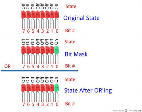
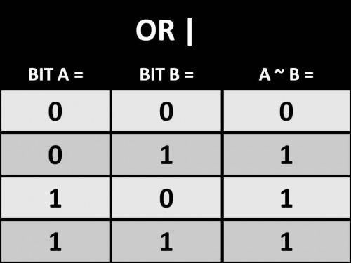
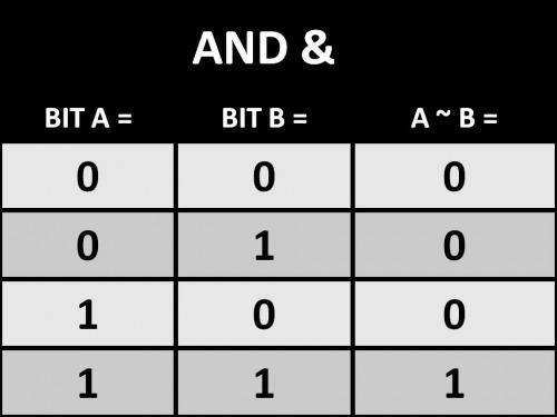
Bitwise operators, like OR’ing, are done on the entire byte. That is, each bit, 0-7, are OR’d, so you have to keep in mind the operation isn’t done only on the bit you want to change. This is where truth tables come in. Below is a table describing the output of the OR operation.
OR (|)
The Left Shift «:
(NOTE: I originally made some mistakes regarding the left-shift operator;6677 has given a very clear description of the left-shift operator in the comments.)
In electronics registers usually have a fixed width. For example, the PORTB registry has the width of 8 bits (0-7). The left-shift operator («) allows you to address a specific bit in a registry, it does this by moving the bits in the registry to the left. The registry itself stays at a fixed width, so when this happens the new places introduced are zero. The bits that get shifted past the width of the registry get detroyed. Going back to the PORTB registry, you could address a different pin besides PB0 by using a shift-left operator. The left-shift operator allows us to quickly create a bit-mask from a byte. In code, this looks like the following:
PORTB = DDRB | 1 << 3;
The above takes the binary number assigned in DDRB and OR’s it with a bit mask that is exactly the same, except the third pin, that pin is equal to 1. Therefore, PORTB would look like this after the operation,
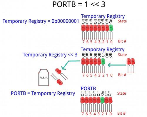
This seems more complex to me, but I understand it becomes very important when you start pulling apart the metal of an AVR.
One last thing, the <avr/io.h> contains defined pin constants. So, this operation,
DDRB |= 0b00000001;
Can be written like so,
DDRB |= 1 << PINB0;
They do exactly the same thing–and I guess the latter is easier to read. Pfft.
The XOR Operator:
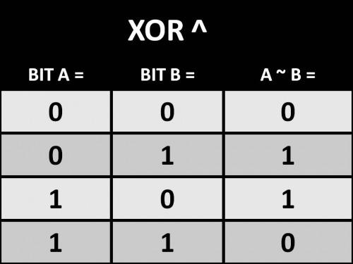
The XOR (^) operator is much like the OR operation. Except, if A and B are equal the result is 0. They are not equal, the result is 1. Here’s the XOR truth table.
XOR (^)
Going back to the LED example, here is the XOR operation.
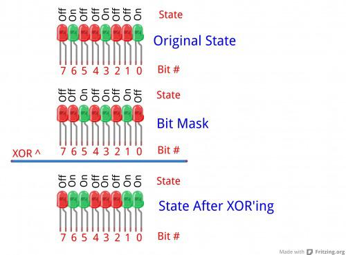
We use the XOR operation to turn the LED off and on. Since a XOR operation on a bit is basically going to set it to the opposite it is in. Therefore, if it is 0 it becomes 1, if it is 1, it becomes 0. This means we can actually shorten or blink code using the operation.
So, our simplified code for Blinkin LED is,
#define F_CPU 8000000    // AVR clock frequency in Hz, used by util/delay.h
#include <avr/io.h>
#include <util/delay.h>

int main(void)
{
	DDRB = 0b00000001;

	while(1)
	{
		PORTB = 0b00000001;
		_delay_ms(500);
		PORTB = 0b00000000;
		_delay_ms(500);
	}
}
And that’s it. That is as far as I’ve gotten. Now, before I move forward I plan attempting to interface a SN754410 and two small motors. I figure, we know how to perform digital pin control and this should allow use to control motor direction, even if we can’t yet control the speed.
Robot Application Note #1: SN754410 and ATtiny1634
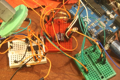
First thing to do is wire up the H-Bridge.
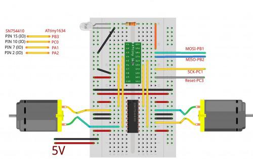
You may notice we wired both “EN” pins to 5v, I don’t know how to generate PWM with AVR yet (but I hope to get there, so I’ll revisit this). Also, I used 5v as both my motor source and the Tiny1634 source. The motors I used were these little guys. I figured since the drop voltage of the SN754410 is around 1.4-2v then I’d be pretty close to the target voltage of my motors (5v - 1.4v = 3.6v). I kept everything approximate to the Tiny’s voltage rating; I figured if I wired something wrong I’d be safer keeping the voltage sources low.
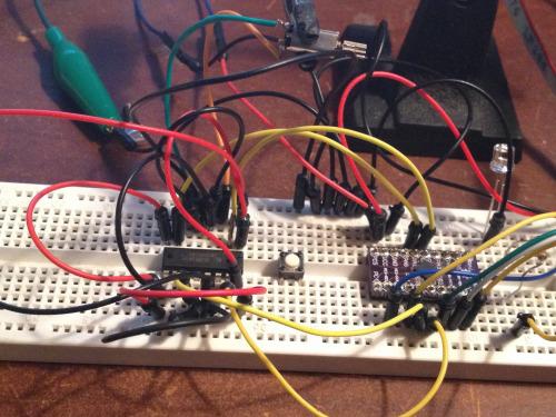
And good call, this is the wiring mess I ended up with…I thought I would start with one motor and move to two.
I began thinking code. I know the basics of the SN754410 and I wanted to be able to hit all the functions of its truth-table.
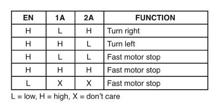
So, I figured all I needed to do was get two of my IO pins to go HIGH and LOW to turn one direction, then switch them to go opposite. This reminded me of the XOR (^) operator, since it did exactly that, turn a bit to its opposite. This is the same operator we used to blink the LED. I ended up with the following code:
#define F_CPU 8000000    // AVR clock frequency in Hz, used by util/delay.h
#include <avr/io.h>
#include <util/delay.h>

int x;
int main(void)
{
	DDRB |= 1 << PINB0; //We set the LED pin to output.
	DDRA |= 1 << PINA1; //Setup motor A IO 1
	DDRA |= 1 << PINA2; //Setup motor A IO 2

	PORTA |= 1 << PINA1; //Set motor A IO 1 high.  Motor A IO 2 will default low.

	while(1)
	{
		// "^=" changes the state of the bit to the opposite of its current.
		PORTB ^= 1 << PINB0;  //LED ON/OFF.
		PORTA ^= 1 << PINA1;  //Motor A starts HIGH, this flips it low, or back again.
		PORTA ^= 1 << PINA2;  //Motor A starts LOW, this flips it high, or back again.
		_delay_ms(500);
	}
}
This code moved my motor one direction, then the other. But there was no pause between the changes of directions. I pulled it a part pretty quick, since I’ve generally had bad luck with instantaneous reversal of inductors.
Well, that wouldn’t do. But I realized another problem. The XOR operator would flip the the pins from high to low, and back again. But how would I set both pins to low? Or both to high? Now, in Arduino C it’s pretty easy, you just write digitalWrite(pin#, HIGH), but in AVR we are controlling bits.
I know I could accomplish this in long-hand, like so:
#define F_CPU 8000000    // AVR clock frequency in Hz, used by util/delay.h
#include <avr/io.h>
#include <util/delay.h>

int main(void)
{
	DDRB |= 1 << PINB0; //We set the LED pin to output.
	DDRA |= 1 << PINA1; //Setup motor A IO 1
	DDRA |= 1 << PINA2; //Setup motor A IO 2

	while(1)
	{
		//This will set the pins high or low, but it does not maintain other pin states.
		PORTB ^= 1 << PINB0; //LED ON/OFF.
		PORTA = 0b00000010;  //This sets PINA1 HIGH, and PINA2 LOW.
		_delay_ms(1500);	 //Wait 1.5 seconds.

		PORTB ^= 1 << PINB0; //LED ON/OFF.
		PORTA = 0b00000000;  //This sets PINA1 LOW, and PINA2 LOW.
		_delay_ms(1500);	 //Wait 1.5 seconds.

		PORTB ^= 1 << PINB0;  //LED ON/OFF.
		PORTA = 0b00000100;  //This sets PINA1 HIGH, and PINA2 LOW.
		_delay_ms(1500);	 //Wait 1.5 seconds.

		PORTB ^= 1 << PINB0;  //LED ON/OFF.
		PORTA = 0b00000000;  //This sets PINA1 HIGH, and PINA2 LOW.
		_delay_ms(1500);	 //Wait 1.5 seconds.
	}
}
This gave me the output I wanted. The motor would turn one direction for 1.5 seconds, then stop, turn the other way, then stop, and start over. Like this:
This code felt bloated to me. And another problem was dawning: What if my LED was on PORTA? That means I would need to keep track the state of three bits (1) bit controlling motor connection A, (2) bit controlling motor connection B, and (3) LED. This means I would need to track 9 possible states (3 pins ^ 2 states = 9 pin states). Now, I might be able to do this mentally, but it would be taxing, especially if my code is dynamically modifying the PORTA registry. But what if all 8 pins were used? 8 pins ^ 2 sates = 64 pin states. Ummm…no. I can’t do it.
It hit me. This is why bitmasks and bitwise operators are so important; they dynamically change the states of one bit, while preserving the states of the rest of the registry. Nifty.
I spent some time with in Newbie Hack’s tutorial: MCU LED Blink tutorial. Specifically, the video there. In it he explains how to use bitwise operators and bit-masks to change the state of a pin while preserving all of the other pin states.
Now we’re cooking.
We already know the bitwise operator (and mask) to set one bit high: OR.
The OR (|)operator sets the a pin HIGH:
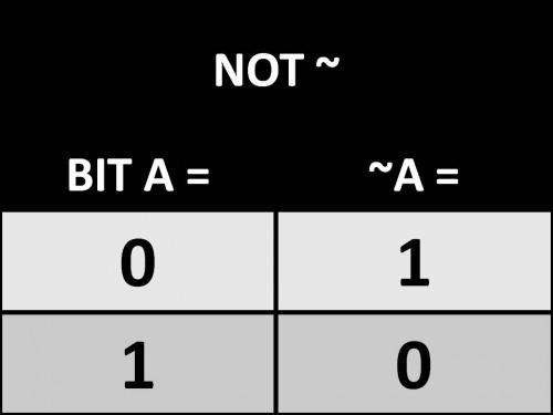
Sadly, clearing a bit while preserving the registry is slightly more complicated. To clear a bit we still use a bitmask, but we use two operators: AND (&) and NOT (~). Their truth-tables look like the following:
AND (&)
NOT (~) is unlike the other operators, it’s simple. It inverts the bit. If 0, it becomes 1, if 1, it turns to 0.
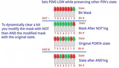
Instead of immediately modifying the PORT state we actually modify our bitmask with the NOT operator. This gives us the inverse mask (00000001 becomes 11111110). We then AND (&) the inverted mask with hte PORT’s original state to clear PIN0 while preserving the other bit’s state. Here’s the LED example for NOT and AND operation to clear a bit:
Ok. I could wrap my head around this. I developed the following code which did what I wanted:
#define F_CPU 8000000    // AVR clock frequency in Hz, used by util/delay.h
#include <avr/io.h>
#include <util/delay.h>

int main(void)
{
	DDRB |= 1 << PINB0; //We set the LED pin to output.
	DDRA |= 1 << PINA1; //Setup motor A IO 1
	DDRA |= 1 << PINA2; //Setup motor A IO 2

	while(1)
	{
		//Sets motor input A LOW, B HIGH.
		PORTB ^= 1 << PINB0;		//LED ON/OFF.
		PORTA |= 1 << PINA1;		//This sets PINA1 HIGH.
		PORTA &= ~ (1 << PINA2);	//This sets PINA2 LOW.
		_delay_ms(1500);			//Wait 1.5 seconds.

		//Sets both motor inputs to low.
		PORTB ^= 1 << PINB0;		//LED ON/OFF.
		PORTA &= ~ (1 << PINA1);	//This sets PINA1 LOW.
		PORTA &= ~ (1 << PINA2);	//This sets PINA2 LOW.
		_delay_ms(1500);			//Wait 1.5 seconds.

		//Sets motor input A HIGH, B LOW.
		PORTB ^= 1 << PINB0;		//LED ON/OFF.
		PORTA &= ~ (1 << PINA1);	//This sets PINA1 LOW.
		PORTA |= 1 << PINA2;		//This sets PINA2 HIGH.
		_delay_ms(1500);			//Wait 1.5 seconds.

		//Sets both motor inputs to low.
		PORTB ^= 1 << PINB0;		//LED ON/OFF.
		PORTA &= ~ (1 << PINA1);	//This sets PINA1 LOW.
		PORTA &= ~ (1 << PINA2);	//This sets PINA2 LOW.
		_delay_ms(1500);			//Wait 1.5 seconds.
		}

}
Code to NOT a PIN looks like this PORTA &= ~ (1 << PINA1);. In plain English and in order of operation, “Set PORTA PIN1 to HIGH, create a bitmask of PORTA, then NOT that bitmask. After, take the NOT’ed bitmask and AND it with PORTA’s original state.”
Whew. I’m not sure I follow that even after writing it. But I understand it. Really, PORTA &= ~ (1 << PINA1) = Set PA1 LOW.
But this is good. We now can dynamically change the state of one PIN without destroying the state of the other PINs on the same port. Booyah!
Alright, let’s go for broke; now that I understand how to set pins HIGH or LOW, I wanted an easy way to control a motor with AVR. I wrote five functions. Four control the states of the motor (HH, LL, LH, HL) and one is a delay function that will accept a variable. The functions can be called from the main loop. Each one expects three parameters, two pin numbers and the number of milliseconds you wish the function to run.
#define F_CPU 8000000    // AVR clock frequency in Hz, used by util/delay.h
#include <avr/io.h>
#include <util/delay.h>

void delay_ms(int ms)
{
	//We make our own millisecond delay function because
	//the _delay_ms does not like dynamic variables.  Meaning
	//you cannot pass it a variable.  By making our own, we can.
	while (ms--) {
		_delay_us(1000);  // one millisecond
	}
}

int forward(int motPinA, int motPinB, int motorFireDuration)
{
	//Sets motor input A LOW, B HIGH.
	PORTB ^= 1 << PINB0;		//LED ON/OFF.
	PORTA |= 1 << motPinA;		//This sets PINA1 HIGH.
	PORTA &= ~ (1 << motPinB);	//This sets PINA2 LOW.
	delay_ms(motorFireDuration);			//Wait 1.5 seconds.
}

int backward(int motPinA, int motPinB, int motorFireDuration)
{
	//Sets motor input A HIGH, B LOW.
	PORTB ^= 1 << PINB0;		//LED ON/OFF.
	PORTA &= ~ (1 << motPinA);	//This sets PINA1 LOW.
	PORTA |= 1 << motPinB;		//This sets PINA2 HIGH.
	delay_ms(motorFireDuration);			//Wait 1.5 seconds.
}

int coast(int motPinA, int motPinB, int motorFireDuration)
{
	//Sets both motor inputs to low.
	PORTB ^= 1 << PINB0;		//LED ON/OFF.
	PORTA &= ~ (1 << motPinA);	//This sets PINA1 LOW.
	PORTA &= ~ (1 << motPinB);	//This sets PINA2 LOW.
	delay_ms(motorFireDuration);			//Wait 1.5 seconds.
}

int brake(int motPinA, int motPinB, int motorFireDuration)
{
	//Sets both motor inputs to HIGH.
	PORTB ^= 1 << PINB0;	//LED ON/OFF.
	PORTA |= 1 << motPinA;	//This sets PINA1 HIGH.
	PORTA |= 1 << motPinB;	//This sets PINA2 HIGH.
	delay_ms(motorFireDuration);			//Wait 1.5 seconds.
}


int main()
{
	DDRB |= 1 << PINB0; //We set the LED pin to output.
	DDRA |= 1 << PINA1; //Setup motor A IO 1
	DDRA |= 1 << PINA2; //Setup motor A IO 2

	while(1)
	{
		//This function spins the motor in one direction for X milliseconds. (L, H)
		forward(PINA1, PINA2, 750);
		//This function lets the motor free spin for X milliseconds (L, L).
		coast(PINA1, PINA2, 1500);
		//This function spins the motor in the other direction for X milliseconds. (H, L)
		backward(PINA1, PINA2, 800);
		//This function brakes the motor for X milliseconds (H, H).
		brake(PINA1, PINA2, 500);
	}

}
Nifty, eh? Now all we need to do is add a second motor and then we can pass the functions the second motor pins and we can use the same set of code to control both motors. Aren’t we efficient!
Some time later…
Well, that didn’t not work as I wanted. I’m tired and didn’t think through how the delay would work in the function. The function would be called for motor A, but motor B wouldn’t be called until A was done. Doh.
Yes, this could be rewritten a hundred ways to salvage it. But! Right now I’m tired, so here’s our working code.
#define F_CPU 8000000    // AVR clock frequency in Hz, used by util/delay.h
#include <avr/io.h>
#include <util/delay.h>

void delay_ms(int ms)
{
	//We make our own millisecond delay function because
	//the _delay_ms does not like dynamic variables.  Meaning
	//you cannot pass it a variable.  By making our own, we can.
	while (ms--) {
		_delay_us(1000);  // one millisecond
	}
}

int forward(int motPinA, int motPinB)
{
	//Sets motor input A LOW, B HIGH.
	PORTA |= 1 << motPinA;		//This sets PINA1 HIGH.
	PORTA &= ~ (1 << motPinB);	//This sets PINA2 LOW.
}

int backward(int motPinA, int motPinB)
{
	//Sets motor input A HIGH, B LOW.
	PORTB ^= 1 << PINB0;		//LED ON/OFF.
	PORTA &= ~ (1 << motPinA);	//This sets PINA1 LOW.
	PORTA |= 1 << motPinB;		//This sets PINA2 HIGH.
}

int coast(int motPinA, int motPinB)
{
	PORTA &= ~ (1 << motPinA);	//This sets PINA1 LOW.
	PORTA &= ~ (1 << motPinB);	//This sets PINA2 LOW.
}

int brake(int motPinA, int motPinB)
{
	//Sets both motor inputs to HIGH.
	PORTA |= 1 << motPinA;	//This sets PINA1 HIGH.
	PORTA |= 1 << motPinB;	//This sets PINA2 HIGH.
}


int main()
{
	DDRB |= 1 << PINB0; //We set the LED pin to output.
	DDRA |= 1 << PINA1; //Setup motor A IO 1
	DDRA |= 1 << PINA2; //Setup motor A IO 2
	DDRA |= 1 << PINB3; //Setup motor A IO 1
	DDRA |= 1 << PINC4; //Setup motor A IO 1

	while(1)
	{
		//This function spins the motor in one direction for X milliseconds. (L, H)
		forward(PINA1, PINA2);
		forward(PINA4, PINA3);
		delay_ms(1000);

		//This function lets the motor free spin for X milliseconds (L, L).
		coast(PINA1, PINA2);
		coast(PINA4, PINA3);
		delay_ms(1000);

		//This function spins the motor in the other direction for X milliseconds. (H, L)
		backward(PINA1, PINA2);
		backward(PINA4, PINA3);
		delay_ms(1000);

		//This function brakes the motor for X milliseconds (H, H).
		brake(PINA1, PINA2);
		brake(PINA4, PINA3);
		delay_ms(1000);
	}

}
Something else I realized. I couldn’t wire motors to a different PORT (my schematic shows PB3 and PC0) since my functions call upon PORTA specifically. Eh, oh well. I’m tired. I’m sure I’ll clean this up over the next few days.
SO! Here’s what we ended with:
Next up! Inputs…ooooohhhh…

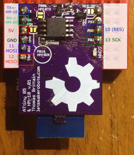
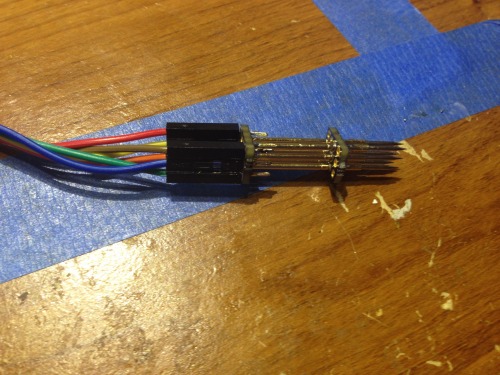
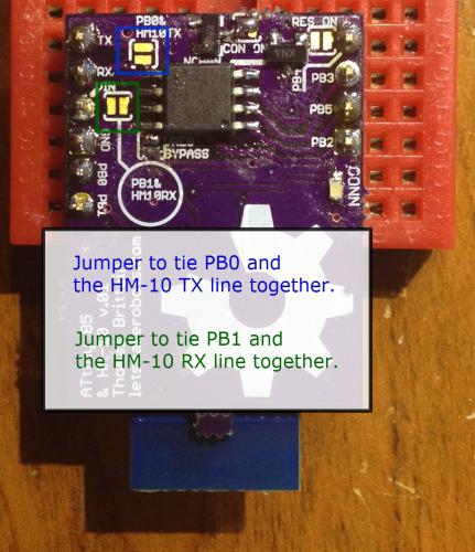 The board is intended to harness the serial connection of the HM-10. In this version I made it straight forward, you leave the jumpers between the RX/TX line of the HM-10 and the ATtiny unsoldered, program the ATtiny as many times as you like. To test your serial connection between the ATtiny and the HM-10 simply breadboard the PCB and put jumpers like so:
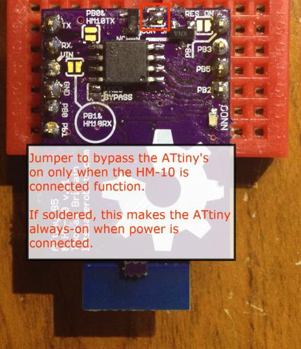 This is an option that’ll probably continue throughout different versions of the board. I ran the GND connection of the ATtiny through a N-Chan MOSFET, and tied the gate of the FET to the PIO1. The PIO1 pin of the HM-10’s function is for a Connection Status LED. But one of the options one can set on the HM-10 is for the PIO1 to stay low unless the HM-10 has a connection. This can be set on the HM-10 when it’s in AT mode by typing:
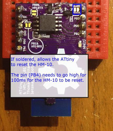 The last solder jumper controls the HM-10’s reset. If soldered, the ATtiny 85 can reset the HM-10 by sending PB4 high for ~100mS. I added this as I hope to create a star-network with the ATtiny Bitsy Spider.
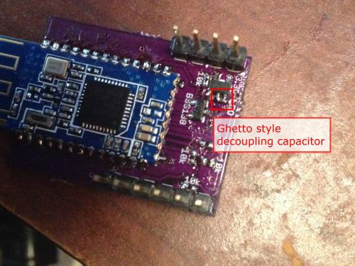
 images
 It’s nothing fancy, but it is a time saver.
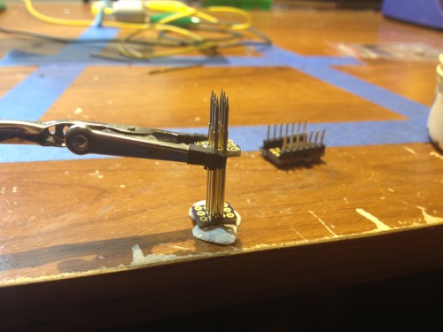
 And here it is in action. It surprised the hell out of me, worked exactly like I wanted it.