I threw this little guy together for my son Silas because he wanted to play with dad’s “Wobot.” There’s not a lot to say about him, he’s a hodgepodge of parts I had lying about:
HDPE Bought at the Dollar Store for $2 (I guess that’s the Two Dollar store.)
3-6v 400 RPM Geared Mini Motors: $8
Two wheels from eBay: $2
4-40 bolts, nuts, and washers (local): $4
Arduino Uno: $9.85
Ardumoto Shield: $11
Bluetooth 4.0 Module: $9
4 x NiHM lying about: $0
1 x Free Sunday morning
Total: $36.85
The first iteration took maybe an hour.
But, after I tossed the little guy together there were a few adjustments. I noticed right away I got this “Oh lord! Don’t drop it!” feeling every time Silas picked him up. Psychology being my profession, I sat on my couch and analyzed it :P
I want my son to spend time with me so I may teach him how to live. I know males often need co-operative tasks to feel secure in their bonding. Therefore, if I’m constantly upset my son is playing with the fruits of my interest he will not share the interests with me. It’s a simple matter of reinforcement. Silas comes into my lab; Silas gets reprimanded; therefore, the behavior of coming into my lab is punished (negative reinforcement) and thereby decreases. This means, for Silas to share my interest, thereby allowing us to bond, I’d need to find a solution to my cognitive dissonance regarding him picking up the robot.
Like most things, I narrowed it down to money. I would get tense because I knew the robot was fragile. It had a mixture of 5 and 3.3v components, and it was still using breadboards and jumpers, I was afraid he’d drop it, it’d break, and I’d lose money.
I couldn’t ask a three-year-old not to pick up a robot; tactual experience is primary for young males, it was an expression of his interest, something I wanted. And I couldn’t make the parts cost less. This left me with only one option**: robustness. **
I vaguely remembered this was a key component of systems theory, but it was one I very often ignored. So, I did what someone who has never had a science would do, I added a lot of bolts.
Video of the “Process”:
Warning: My son is worse than Matthew McConaughey about wearing shirts. Hey, we try, boy’s just proud of his belly.
At the local hardware store I bought some 4-40 bolts and nuts, and started revamping the little bot.
In the end, I really didn’t do anything fancy, as apparent. I drilled holes into the battery plastic-case, that aligned with holes in the robot base, and bolted it together. I, for the first time, used the mounting holes in the Arduino Uno, bolting it to the base. I then “designed” a hood (bonnet) for the little guy. from match HDPE, making sure to bolt it down as well. Lastly, I sealed the motor-gears with electrical tape and put a few drops of oil in them. I noticed this regarding geared mini-motors, they collect hair and will strip out the gears.
In the end, I did nothing a second grader would be proud of, but I did force myself to drop it from hip heigt five times to make sure I was over the “Oh Shiii-nobi Ninja!” feeling. In psychology we call that systematic desensitization. Or something as equally important sounding.
It collected so much hair the tires poped off.
Bleh.
I was careful not to wrap too much of the motor, since I had the thought it might decrease thermal exchange.
UPDATE (2/514): I split this post, since it’s getting a little sluggish. I’ve updated the breakout board versioÂn v.9.9, have instructions for updating the firmware, and added some research notes on a pseudo-Star-Network.
UPDATE (11/23/13): I’ve added research notes on networking the HM-10s and an ATtiny 85 serial filter (at bottom).
OLD:
I know there are few Bluetooth 4.0 and Arduino solutions coming out. Redbear Labs’ BLE Shield, the BLEDuinoe Kickstarter projects, and the Bluegiga Shield. But I didn’t really like these due primarily to the price:
Redbear’s Mini: $39.95 (Note: This is a uC and BLE combo).
Redbear’s Uno Shield: $29.95
BLEDuino: $19.95 (if part of Kickstarter)
Bluegiga Shield: $69.95
These are out of my price range for a single module. So, in the end, I created a breakout for a cheap module and got it interfaced with the Arduino for approximately $10.03 a module. Although, this price will be higher if you don’t buy components in bulk.
Here’s a Video Summary:
Now, I’ve not interfaced these with iOS or Droid devices, they are simply a Bluetooth 4.0 solution for a wireless serial connection. I’ve interfaced these devices in a limited way with iOS. I used the LightBlue App on my iPad Mini to open a rough serial interface. Though, I’ll probably do this later with Jellybean 4.3’s Bluetooth 4.0 API. UPDATE: I’ve discovered jnhuamoa provides sample iOS 7.0 interface code for the HM-10.
Proof of Concept Video
Now, if only I had the $99 to pay for an App store publisher license, I’d make us all a nice little robot interface :)
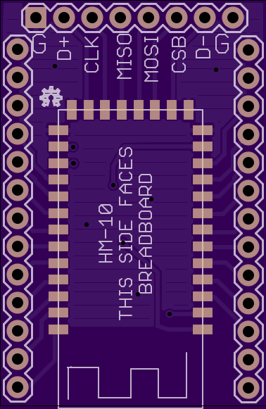
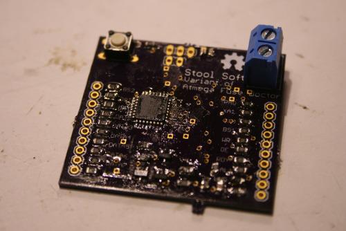
The modules I used were these HM-10’s. I won’t go into making the breakout board, since I did that already. I will state, though, the last iteration of the breakout boards I made had mistakes that I was able to correct for home use, and I’ve corrected them in the Eagle files I’ll put up, so the board files I put up are untested, though, they are on the way and when I’ve confirmed they work I’ll post a confirmation. Also, the images I have of the boards I’m using are different, since I corrected the board files. UPDATE: It has come to my attention the traffic LEDs on the RX/TX lines are always on due to the level converter pulling the lines high. The board still functions as intended if the LEDs are left unpopulated.
Ok. Let’s make a breakout…
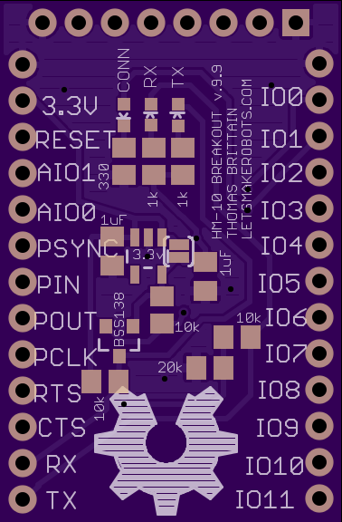
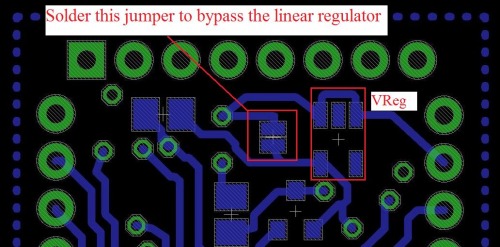
1. This is the v .9.9 of my breakout. I do not swear it is bug free, but it seems stable. Working traffic LEDs and it uses a linear voltage regulator:
(OPTIONAL) SOT-23 LDO Voltage Regulator (it doesn’t make sense to use this, but I put the option on the board just in case. I’ll explain).
Again, I bought pieces in bulk, since I know I’ll use them on other projectss; my price per module is $10.03. Of course, you can buy all these components on DigiKey but the price will be bit more.
Ok. Let me explain the 3.3 linear regulator. I added this option to the board in case there is no pre-regulated 3.3v source, but it inherently contradicts the purpose of using a Bluetooth 4.0 module: extremely low power consumption. I tried to get a reading on the milliamps the HM-10 pulls, but my multi-meter only goes to the tenths (ma) and the module wouldn’t show at all, even during active use. And as many (all?) probably already know, the linear regulator is extremely inefficient. So, it’s much better to solder the jumper that bypasses the regulator and leave it un-populated. UPDATE: I’ve found info on power consumption:
Other important soldering tools: A wet sponge and brass-ball will keep your fine soldering tip _fine. _Sponge the solder tip, then run it through the brass-ball after each component to prevent build-up.
To speak blasphemy: Flux is ok, but I find the tweezers often take place of the flux.
Practice using both hands during soldering. Tweezers in one and solder-iron in the other.
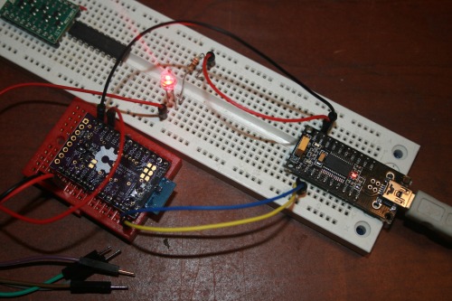
5. Wire it up to serial port.
So, this is the board I screwed up on. Basically, like a dumb-ass I was trying to regulate 3.3v with a voltage divider. Of course, I know better now. Still, given the HM-10 pulls fewer than 10ma, I’ll probably go back and run the math to see if as voltage-divider is, in fact, a feasible solution.
Anyway, the hookup is pretty simple.
BT-3.3v <—> 3.3v
BT-RX <—> FTDI-TX
BT-TX <—> FTDI-RX
BT-IO1 <–> LED <–> 220 Res. <–> GND
BT-GND <—> FTDI GND
(For the 3.3v I used a regulator and tied my grounds).
A few notes, the RX and TX lines are translated from 3.3v to 5v by way of a voltage divider and the BS1138. All other lines will die at >3.3v.
Now, as I’ve stated, I’m connecting two modules together, so you have to set one module as the slave.
Then, under the “Send” tab type in AT commands and hit “Send ASCII”:
Send: AT
Response: OK
Now, setup one unit as the slave (they default as master).
Send: AT+ROLE1
Response: OK+Role:Slave
That should be all we need to do to setup the connection. Now, whenever they power on they will automatically try to mate. You’ll know if they are connected if the LED goes from blinking to solid.
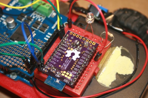
7. Wire the modules to the target devices.
BT-3.3v <—> Arduino 3.3
BT-RX <—> Arduino TX
BT-TX <—> Arduino RX
BT-IO1 <–> LED <–> 220 Res. <–> GND (or if you’ve soldered on the 0603s you can skip that connection).
Notice the mistakes routing my board? :(
It was salvageable though.
10. Turn on the devices and make sure the LEDs go solid.
(10a. Yell at me if it doesn’t work.)
11. If the LEDs go solid, then you have a serial connection between the devices. Have fun :)
Some things I’ve discovered:
They have much better range than I would have thought. I’m getting around 30ft indoors. I’ve not tried them outside. For those of you who’ve read my developing post: Yes, having the copper planes underneath the antenna is what caused the range issue. They’ve got super range now :) UPDATE: I found info on range: 60 feet indoors, 300 feet line-of-sight.
They connect much faster than older Bluetooth devices.
Actively sending or receiving draws fewer than 10mAs :)
I love these little guys over Xbees :)
Research Towards a Hub and Node network using the HM-10s:
11/18/2013
The Theory:
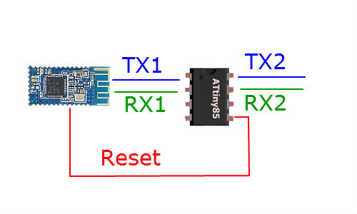
So, I’ve been working on putting an ATtiny 85 at the end of the HM-10’s serial line to allow for remote control of AT commands. It goes something like this:
Using Software Serial to setup two serial lines. Basically, the ATtiny 85 acts as a filter on the serial line. If it is a regular message it passes from TX1 to TX2. But the code in the Tiny will be looking for serial data that begins with “AT+” and if it sees something, it will instead write that command to RX1.
Now, stick with me a minute.
The Master has a mode called Remote, which is setup with the command AT+MODE2. While in Remote mode the HM-10 will transmit serial data but also accept AT commands. Sadly, this seems to only work on the Master. So, we must have a different setup for the slaves.
In the case of the slaves we use the reset line. Each slave will have the ATtiny filter, but when it gets an “AT+” command in the serial data it will pull the reset line low. This resets the HM-10. We do this because the HM-10 has a command AT+IMME1 and this will put the HM-10 Slave into a mode where it wont automatically seek to pair. Instead, it will accept AT commands until given the command “AT+WORK” whch will send it into pairing/transmission mode.
Ok. Going back to our Slave setup. So, when we setup our HM-10/ATtiny combos as Slaves, we put them all in the mode where they don’t seek to pair until given the command AT+WORK. Of course, we program the ATtiny to send the HM-10 into pairing mode whenever it is turned on. Then, once it pairs with our Master we can send a serial message through the Master to the Slave with the string, “AT+RESET&AT+PIO11&AT+WORK” When the ATtiny gets this code it will pull the reset line low, putting the Slave back in AT mode. Then, the ATtiny connected to the slave will send the command AT+PIO11 which puts pin 1 on the HM-10 high. After, the ATtiny gives the command to the Slave to re-enter transmission mode. Voila.
Alright, so far, I’ve got all that coded and the hardware worked out–most everything above I can confirm works.
But, I’ve been skeptical as to whether or not the HM-10 will connect quick enough for a Master to have a seemingly seamless transmission between Slaves. I derived this skepticism from watching the blinking connection LED everytime I reset one of the HM-10s that was formerly paired. Then it hit me. They weren’t immediately reconnecting because the Slave still thought it was connected, therefore, the HM-10 firmware had not re-initialized pairing protocol. I tested it. And sure enough, if a Master and Slave are paired, one loses power, then the other will hang for 3 seconds before trying to pair again. But, if one loses power and the other one is reset at the same time, when they both power back on (<100ms) they will almost immediately pair.
Booyah!
So, all we have to do is setup a code where a Master connects to a node, tells it what it needs to, then tells it to reset itself,. Afterwards, the Master changes its own pairing pin, then resets itself, whenever the Master comes back up it should almost immediately connect to the new node.
And there we go. A viable Bluetooth 4.0 Star Network. I hope to have this fully tested before the Holidays.
11/23/13
(Warning: Lots of vehement expression towards datasheet-writers)
Ok. So here is what’ve I learned.
Alright, I’m beginning this article by saying; I love the HM-10. Excellent device. However! I want to beat the ever loving poo out of their datasheet writer. To begin, I’ve ordered several HM-10s from www.fasttech.com over the course of several months. And it never dawned on me they were upgrading the firmware quicker than I could buy them. This wouldn’t be too bad, but it’s like the HM-10 monster took a poo and the datasheets are the result: actual commands for listed firmware versions don’t match the datasheets, there is different information in the Chinese datasheets than the English, some AT commands have been merged without being stated. It’s just fubar.
So, some of the issues I’ve had trying to network the little devices I believe has come from firmware versions not playing nice.
For example, the HM-10 V303 has a command AT+IMME1 (0 to turn it off) for the Master only that keeps it in AT mode until given the command AT+WORK. I discovered that stupid-ass jnhuamao changed the firmware at some point (in the 4xx range) and this command merged with AT+START, which in my V303 datasheet is a command for something else. F’in poor translation.
Now, I have 2 boards with firmware V303 and 1 board with V502. I also have 2 modules that I bought later which more than likely have something greater than V502. I’m praying they are V508 or greater; at V508 they added the feature to upgrade the firmware through the serial line. ‘Bout damn time.
I can’t find the datasheets (in either language) for V502, but looking at the V508 I can see the AT+TYPE command now has three options. The V303 lists only two options for AT+TYPE. Yet, somehow, my V303 boards actually take this third option (AT+TYPE2). Bizarre.
Moving on from the firmware and datasheet mess: Using the ATtiny 85 does work, but to get the HM-10 to take the commands it requires:
TinySerial.write(“AT+xxxxx”);
So, in theory, to get a HM-10 Master setup to only enter transmission mode when given a command, it goes something like this:
TinySerial.write(“AT+RENEW”); //Reset to factory settings.
TinySerial.write(“AT+ROLE0”); // Be the Master.
TinySerial.write(“AT+IMME1”); // Don’t enter transmission mode until told.
TinySerial.write(“AT+RESET”); // IMME takes effect after reset.
TinySerial.write(“AT+”START”); // Ok, try to connect to something.
This resets it to factory settings, tells it not to connect until given the command, then it gives the command to start trying to connect.
Here’s example code I use on the ATtiny 85:
/*
This code has been modified for use on an ATtiny.
Created by Matthew on June 11, 2013
http://projectssfromtech.blogspot.com/
This example code is in the public domain.
*/#include
SoftwareSerialTinySerial(3,4);// RX, TXSoftwareSerialTinySerial2(1,2);// RX, TXStringblah;intincomingByte=0;voidsetup(){// Open serial communications and let us know we are connectedTinySerial.begin(9600);//Serial line for the ATtiny85 to read/write from/to the HM-10.TinySerial.println("Tiny Serial Connected via SoftwareSerial Library");TinySerial2.begin(9600);//Serial line for the ATtiny85 to print to a serial port.TinySerial2.println("Tiny Serial Connected via SoftwareSerial Library");TinySerial.write("AT+RENEW");// Reset all settings.delay(300);TinySerial.write("AT+ROLE0");// Slave mode ("AT+ROLE1" is slave and "AT+ROLE0" is master)delay(300);//TinySerial.write("AT+PASS001111"); // "AT+PASS001111" sets the password.//delay(300);//The work mode only works for the Master HM-10.TinySerial.write("AT+MODE2");//"AT+MODE0" = Transmission Mode, "AT+MODE1" = Remote Control Mode, "AT+MODE2" = Modes 0 + 1.delay(300);TinySerial.write("AT+IMME1");// Don't enter transmission mode until told. ("AT+IMME0" is wait until "AT+START" to work. "AT+WORK1" is connect right away.).delay(300);TinySerial.write("AT+START");// Ok, go ahead and enter. BULLSHIT! Apparently "AT+WORK" is not what we use, it's "AT+START"delay(300);}voidloop(){}
Ok. I also learned a little more about PIN command. To begin, “AT+PASS000001” will set the PIN, not “AT+PIN000001”. Of course, it must be a 6 digit number, so, fill the others with zeros. Now, depending on the firmware version there are 3 different settings for PIN pairing, all set by AT+TYPEx
AT+TYPE0 – this is supposed to be “Connect without password mode”
AT+TYPE1 – “Simple pairing” (no explaination).
AT+TYPE2 – “Requires PIN for pairing”
Alright. So, this was the key to my switching between modules. I thought I would set a unique PIN for each slave and the ATtiny 85 connected to my Master would switch the PIN on my Master depending on which node I wanted to connect. Well, this feature is broken. I played with it for several hours and no matter how I set the PIN or TYPE settings, the modules would pair even without the correct pin. I could find no answer for this behavior. Until, I read through the Chinese version of the datasheet and came across this gem.
“IMPORTANT: V515 previous versions, the directive no practical effect, after setting causes not connect, please do not use.”
Of course, this is a Google translation. But I’m pretty sure I read that, “This feature on versions under V515 does not work.”
And that’s where I am at the moment. I wanted to make sure I wrote some of this stuff down in case others were running into problems. My next projects will be writing to jnhuamao and get some questions answered (e.g., “Any way to get upgrade the firmware on versions less than V508 so I’m not left with 5 unsecure HM-10s; maybe through the SPI interface?).
I’m posting this collection out of frustration and perhaps defeat. I’ve been working on several projectss for the last two months, trying to finish something. I’d gotten addicted to that “It works!” moment I think anyone gets when they see a LED blink. Sadly, I feel I’ve failed at most of these projectss.
The second reason I post is posterity.
I’ve grown to appreciate failure, given how much I learn from it. Of course, I’d much rather learn from other’s failures. So, I figure I’d try to write up all my blunders for others.
The last reason is tactical humility.
I figure I might be able to finish some of these projectss if someone tells me what the hell I’m doing wrong (though, it might take less time if someone tells me what’s right).
Alright, enough self-loathing and belaboring.
Contents:
Arduino heart rate sensor.
Bluetooth 4.0
Heatsinking a high-power LED
XL4432 – long-range RF
SMD version of Atmega Fuse Doctor
Arduino Thermostat
Raspberry Pi and Remote Compiling
Pulse Sensor Re-Creation – A Story of Heartbreak:
Pulse Sensor Attempt 1:
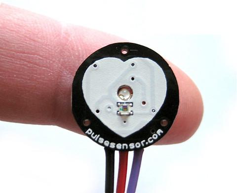
For a awhile now I’ve been interested biometrics. I figure if my wife ever finishes graduate school and becomes my sugar-momma, then, I’ll pursue my pin-headed dope in Experimental Psychology. Developing my own sensors, or at least having an intimate knowledge of how they work would probably help me getting into a program (damn education inflation). So, I’ve been watching out for open-hardware sensors for a bit, and it seems these guys pulse-sensor was ever increasing in popularity.
As always, I still believe the best way for a dumb-guy like myself to learn smart stuff, is by taking apart stuff the real smart-people make. But being a non-conformist, I avoided trying to re-make their sensor. Still, after viewing other schematics I found (1, 2, 3, 4, 5), I decided I’d be such a non-conformist I’d conform and go with the popular sensor.
After a glance, it seemed great; a small lightweight heart-rate monitor that was Arduino compatible. Then, I noticed the design files were put together in Design Spark. “No problem, I thought, I’ll just export them over to Eagle, then I can play with the PCB layout, maybe switch those 0603s to 0805s and send it off to OSHPark.”
Come to find out there is no easy way to export Eagle files from Design Spark.
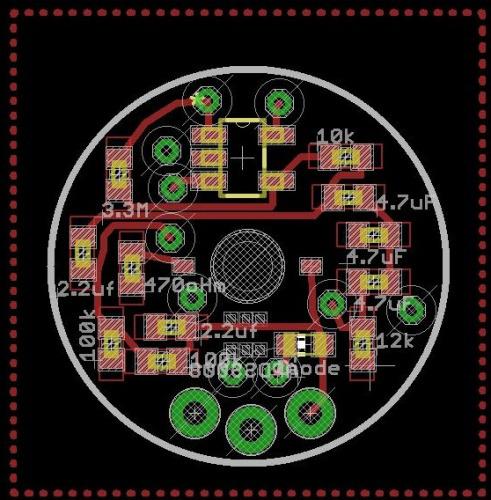
New plan, I’ll just follow the Pulse-Sensor schematicand re-create the entire board in Eagle (all half inch of it). And that’s what I did. I’d post those Eagle files, but, they suck and don’t work. I had made several major mistakes.
To begin, I had to create several Eagle components for the board. The op-amp, LED, and light-sensor. Respectively, MCP6001, AM2520ZGC09, and APDS-9008. None were a real threat. I made each part according to the datasheets. Then, I strung together the schematic in Eagle, switched to the PCB layout, and threw my pieces down. But for some reason I thought, “I should replace the 0603 passives on this board with 0402s.”
I figured, if I could shrink the board even more I’d be happier, right? I mean, smaller is better–so the women say. Well, it was the only thing on this board version I didn’t regret.
In the end, the board was sent off to OshPark for a $2.00.
When the post came, as my friends across the lake say, I was excited about the itty-bitty board. Unfortunately, I started my string of disappointments after I populated the board.
Like I said, I didn’t regret the 0402s at all. They all soldered on pretty easy. Though, I think my primary beef with 0402s over 0802 is when it comes to tweezerless soldering. See, when I go to solder 0802s I have this process of tapping one pad with a bit of solder, and taking a resistor for example, hold the 0802’s body with tweezers in my left hand while my right hand keeps the solder warm. Then, I simply run one end of the resistor into the pool of solder, move the iron away, then, when the solder cools, let go with the tweezers. To get the other end, I’ll put the tweezers down and simply tap the other end with solder. Voila.
I’d try to get a picture of this process, but, I don’t have a third hand yet. Though,these folkare working on it.
This doesn’t work with 0402s. One, holding the body of a 0402 with tweezers is like a giant trying to tight-rope-walk a piece of dental-floss. But the problem really begins in the second step, when I set the tweezers down to tap the other end, the heat from my iron shots through the little 0402 to the other end, loosening the hardened side, as soon as this happens, the entire 0402 stands on end, hugging my iron. Of course, this ends with me quickly pulling the little guy off with my fingers (not smart, but each 0402 is like $.20).
A few notes:
The LED fit through the hole in the PCB, but I was worried the drill wouldn’t be wide enough (I guessed a bit).
OSHPark takes non-squarish shapes, though, they charge you as if it were square.
Open-source hardware is not the same as Open-Source (but lacking some key pieces of information) Hardware. I believe the Pulse Sensor is the latter.
The only piece that couldn’t be soldered with a solder-iron was the light-sensor. All of it’s pads are tucked under the actual component. So, I used the good ole’ overturned clothes-iron.
Anyways, once I had all the components in place? I threw on a few wires, attached it to the Arduino, uploaded the sketch, turned it on. And…smoke.
Waah-waaah.
I’d like to tell you this story has a good end. But, like the title suggests, it’s an incomplete work.
I started trouble shooting the board: I checked the wiring, the schematic, the Eagle components I made. I tried 3.3v, different sketches, touching the sensor, not touching the sensor, praying to Cthullu. Nothing. Just pretty smoke.
Finally, I gave up.
(Well, as much as I ever give-up on anything. Stupid obsessive nature.)
Pulse Sensor Attempt 2:
Well, weeks passed and I was working on other projectss, but the little pulse-sensor board kept begging for another chance.
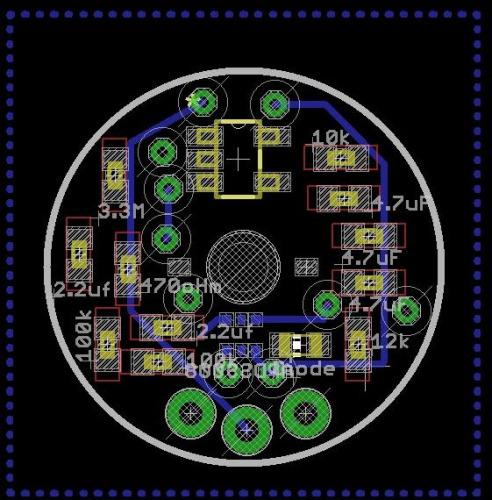
I decided to try again. I’d have no more trying to ignorantly trouble-shoot the thumbnail sized board, so I went back to the designers’ original files, downloaded DesignSpark, and pulled up the schematic and board. After briefly examining them I began to realize I was a little off on the board layout. Then it hit me, I could always copy the design manually, it shouldn’t take long since I had the schematic already together and the components made.
Well, below is a video of that process:
After I caught the two errors (wrong MCP6001 and disorientation of the APDS-9008) I felt a little better sending it to OSHPark again. Two dollars later I wasn’t as sure, but the boards were on their way regardless. While I waited, I jumped on Texas Instrument’s website and ordered samples of (what I hoped was) the correct op-amp.
When the boards came in I did something frugal that made me kick myself later: I pulled the components off the old board to put on the new board. It sounded like a great financial strategy at the time, but added more work when I realized my new little board still didn’t work. Now, I had to question whether it was the components, the board, or I also ran into this articlethat scared the crap outta me. Although, it gave me a lot of respect for those guys. Re-soldering 2,000 SMD leds in a night was no small task. And perhaps it welled slight guilt in me since I was working hard to circumvent their more than deserved profit off their $25 sensor.
That’s pretty much it: So far. I’ve not had the time to give her another go, but I will. The next round I’ll actually create breakout boards for the main components to make sure my soldering is not the problem. I’m really only concerned with the light sensor, since the pads are practically DFN (no exposed legs). But I hope to have this tied up in the next week to month.
If anyone knows me, they know I’m cheap. But I prefer to think of myself as “resource efficient.” This has led me to do a bit of shopping at FastTech. Their stuff isn’t as cheap as the eBay, but pretty damn close.
Well, that’s a prelude to this story. Awhile back a co-worker’s head-phone jack on his phone broke. He said, “Don’t you fiddle with that stuff? You should just make me a Bluetooth headset.” Externally: Joke-deflected. Internally: Challenge-accepted.
I started looking through different Bluetooth ICs. I mean, why buy Bluetooth ear-phones for under $20 when you could make a set for twice that? Especially, when only takes around a 100 hours of “fiddling” time? Americans are so lazy.
Well, the first IC I landed was this guy: LMX9838. And it wasn’t until I had finished the Eagle part, designed the schematic, and was working on the board did I look at how much it retailedfor. Well, I wasn’t going to order samples every time I wanted to embed Bluetooth in my projects, besides, isn’t Bluetooth 2.0 power hungry?
Well, back to looking through ICs.
And on the second browsing I ran across Texas Instrument’s new CC2500series. Righteous.
I saw the possibility of making a Bluetooth 4.0 device with this little chip CC2540. It’s a SoC (system-on-chip) with Bluetooth 4.0 capability. Again, righteous.
I ordered several samples of the chip from TI. While I waited on the post I began wading through all the terms: BLE, BT 4.0, Smart Energy, etc. I searched to see if anyone else had already created the schematic, PCB, and firmware that would be needed to drive these little guys. Here are a few discoveries I made.
Hardware:
Here’s a complete PCB for the CC2541, which seems to be optimized for low-power consumption. I will say, the entire chip is pretty well documented on the TI forums, but overall, the hardware aspects are the least.
I downloaded the Eagle files and began ripping off all the unnecessary circuits. (I think there is a lipo charger circuit?) The goal was to bring the board size small enough it would be cheap to print.
But as I got to ripping pieces of close to the antennae noticed how easily it would be to screw the whole thing up. And since I hadn’t built my spectrum analyzeryet, I would be stabbing in the dark each time ordered a version of the board.
This realization on top of all the 0402s and the DFN package, well, I decided I wanted to play with the chip on a completed board, with already installed firmware before I sunk time into a personal development (fancy words for: I got lazy).
I won’t cover the firmware or software, since I took another route and didn’t thoroughly Google-search them. But do know, within the collective in the Texas Instrument’s cc2500 forums there is almost everything you’d want. Although, be prepared, if you desire to create your own firmware you’ll need to brush up on your C and AVR programming.
This brings me back to Fasttech.
I noticed one day they had these HM-10s on sale. Waahoo! A pre-designed CC2540 board with firmware already created? Firmware that is AT commandable? I bought two.
I figure I could at least get a feel for the chip and see if it was something I really wanted to sink time into developing.
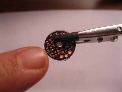
Well, a week later I got these little guys.
They aren’t bad little boards. But, they were little. I tried soldering on jumpers to the ant sized grooves, it didn’t go well. I knew to really start playing with the board I needed a breakout.
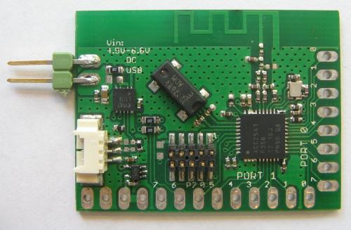
When the breakout boards came in I was surprised they worked (I’m usually surprised when something I make turns out :).
They straddled my breadboard nicely. And it allowed me to play with all the bits of the board I wanted: V, GND, Rx, Tx, and PIO1 (pin for connection-status LED).
Since the little HM-10 operated on 3.3v I carefulIy put it in the breadboard and pulled out my Sparkfun Lilypad FTDI (first huge mistake) to interface with the board’s serial.
Well, I couldn’t figure out what was wrong; the board would not respond to AT commands (I was using Realterm). I mean, I had plugged the 3.3v into the HM-10’s power, so I know it wasn’t getting too much voltage. I even checked it with a multi-meter (about a hundred times).
Well, as those of you who are smarter than me (so all of you?) probably already know: The Sparkfun’s Lilypad FTDI is designed to provide the Lilypad with 3.3v, but the Atmega-328-P on the Lilypad is actually 5v tolerant. So why drop the voltage on the Rx and Tx lines? Of course, this wasn’t a conclusion I came to for many hours, really, until I started randomly probing the boards with the multi-meter.
Damnit.
Well, there goes $13.98 (yes, I was slow enough to kill both boards).
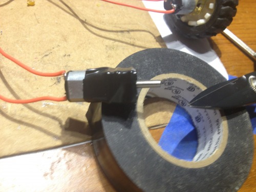
When everything came in, I took the broken boards off by heating the bottom of the breakout with a heat-gun until the HM-10 was loose. I cleaned the top of the breakout boards with some solder wick. Then, soldered the new HM-10s on.
Video of Soldering the HM-10 to Breakout
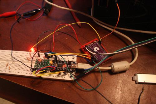
I wired the whole mess up on a breadboard and was surprised when I actually got a response in Realterm.
AT
AT+OK
**Victory! **(hey, I’ve learned to enjoy even small triumphs)
I had to use specific settings in Realterm to successfully communicate with the HM-10
Under the “Port” tab
Buad: 9600
Parity: None
Data Bits: 8
Stop Bits: 1
Hardware Flow Control: RTS/CTS
Software Flow Control: Receive–Yes, Transmit–Yes
Under the “Echo Port” tab
Echo On: Yes
Monitor: Yes
Then, under the “Send” tab typed in my AT commands and hit “Send ASCII”:
This worked pretty well. Every time I typed “AT” it shot back, “AT+OK”
So, I started digging for the rest of the AT commands. And dig I did.
Apparently the HM-10 is developed by www.jnhuamao.cn. These folk are somewhere over in Jinan’s Hi-tech Development Zone. Anyways, luckily we have GoogleTranslate and I was able to get through several of their current documents. But not before I lost a time on trying to get the module to respond to AT commands no longer supported (like the connection command).
The manual answered a lot of my questions. It came with a complete pinout (even a schematic!). After playing with the commands I was re-naming the module, resetting it and running many other needed commands.
Now for a live test.
I got my work phone, iPhone 4S, which is equipped with Bluetooth 4.0. I tried using the stock Bluetooth connection found under settings and it couldn’t find my little HM-10. I switched to LightBlueand was able to not only find my little module (named Bob), but it connected, and allowed me to send serial data to Realterm! Success.
I thought I was on my way to slapping these little HM-10s on a robot, plugging a Bluetooth 4.0 dongle on my PC, sitting back and letting magic happen. That’s not quite how it worked out. I ordered thisBluetooth dongle and when it came in quickly discovered that the drivers needed to provide it with magic powers were not available. I tried it all, TI’s tool pack, random internet drivers, shady internet drivers. It simply wasn’t going to happen with that dongle.
I figured that’s what you get buying the cheapest dongle you can find. So, I switched over to Newegg and bought thisdongle, making sure it came with supported drivers.
When I got it in, it still didn’t work (I believe this is completely a software issue, so I expect different outcome if I were to play with these dongles on a Linux machine).
I thought, “Well screw it, I could always make a microcontroller, RS232, and another HM-10 into my own dongle.”
Um. But I couldn’t figure out how to get two of the modules to connect. I set them both up on a breadboard, and they both had the little blinking LED (meaning not connected), but the little guys just wouldn’t get it on.
So, on a whim I emailed Jnhuamoa and asked.
Hello,
I’m currently working on interfacing two of your HM-10 modules. I’m having trouble because there seems to be no pairing command. I use “AT+VERS?” and it tells me I’m using version HMSoft V303. Is this old firmware? If it is, is there newer firmware available I could download and write to the cc2540? I’ve looked through your website and I cannot seem to find any firmware upgrades. But, I only read English, so I’m curious if I’ve missed it in translation.
I appreciate any help you may give,
–Thomas Brittain
To my surprise, they responded
Dear sir
Thanks you for choose our products.
Between two HM-10 modules, pair and connect process is automic.
You only need to make sure that one of the HM-10 module set to master mode, another is salve mode (use AT+ROLE command), and the TYPE setting of the two modules is the same (use AT+TYPE command) and the PIN number is also same (use AT+PASS command).
If the master module has connected to other modules, please execute AT+CLEAR command first.
Our website have module work flow chart, you can have a look.
:)
Best regards
HMSoft
guocg
But…now what? I mean, I could wire the guys up to an Arduino-bot but it would be one dongle per robot. What I had wanted was several Bluetooth bots per one dongle.
To be honest, I never expected to use the Bluetooth as a bot tether, I was just looking for an application other than my co-workers ear-phones.
After reading the manual some more, and tinkering with the AT commands, I sent another email over to Guocg.
Good sir,
Thank you for your quick reply.
I felt stupid after your instructions. I had the HM-10 paired in less than a minute. A very simple process. Thank you.
But I do have a few others questions. Is there any way to have more control over the connection process? I’d really like to have a micro-controller (PIC, Atmega) in between give the HM-10 very specific commands, which would involve the master connect to several slaves depending on the need of the master. I can see how the PIN could be changed, but would it be fast enough for one master to manage several slaves in real time?
This is the process I’m going to attempt:
1. Setup 3 slaves with unique PINs
2. Setup 1 master connected to a microcontroller.
3. Set master to AT+IMME0 (work when given the command).
3. The micro-controller will pull the HM-10 reset line then give the following commands:
a. AT+CLEAR
b. AT+PINslave1
c. AT+WORK
4. The micro-controller will send a ‘X’ to slave1
5. Slave1 will have a micro-controller pulling the reset line every half a second or so, unless, it gets a connection with the ‘X’ string.
I’m not sure of the speed of this process, but I believe it would let me switch between modules remotely. I have read about some of the older releases of the firmware for the module HM-10. Is there still no chance in getting those? I understand now that pairing with the HM-10 modules is very easy, but it also seems very restricted.
Thanks for all the help,
–Thomas
This time, I think I got a blow-off response. That’s fair. I’m a hack not an industrial developer.
Dear sir
You shoule make sure that HM-10 modules AT+TYPE vlaue is 1. PinCode set command is AT+PASS.
Best regards
HMSoft
Guocg
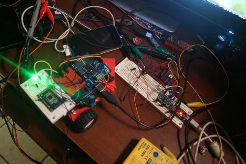
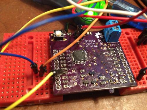
So, no chance on getting older firmware. I started preparing to implement my Atmega & HM-10 team. I strung up the HM-10 on the backpack breadboard of Silas’ bot (my son’s bot).
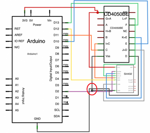
I was beginning to get really frustrated with the level conversion problem. I had tried the CD4050, but found it was uni-directional, meaning I still had to have a converter for the Rx bus (HM-10 and Arduino), or, unplug the HM-10 from the Rx bus every time I wanted to upload a sketch to the Arduino. In the end, I started doing that and used a voltage divider for the Tx line.
That’s when I ran into another problem: Range.
More specifically, the lack of range. The little modules would lose connection if more than 7 inches away. Ugh.
Back to trouble-shooting. I couldn’t really pin-point the problem. I did find the modules had a power setting (AT+POWEx, X=0-4). But no matter what setting I put the modules on, they didn’t have range greater than 7 inches. But I did notice when I was moving the slave around I could get a connection by aiming the master towards the slave. But if I rotated the module, it would lose connection. I didn’t want to do it, but I started reading about telemetry.
I can’t say I learned anything, though, I did develop a theory. The ground planes I put on my breakout board were screwing with the telemetry.
A second time I breakout the heat-gun and pull the HM-10s off their breakout boards. I get back in Eagle and re-design the breakout to remove the ground planes underneath
I thought as long as I was going to have the boards printed again, I’d go ahead and add some sort of level conversion. I reviewed a few different SMD chips (CD4050, 74LVC245, TXB0108, etc.) but I found the chip was either uni-directional or overpriced. In the end, I decided on the same design as Ada’s and Spark’s 4-channel I2C converters.
This design was cheap, scalable, and required little layout room. It was fairly simple, voltage divider from high-to-low, and a tricky little N-Channel MOSFET on the low-to-high. The low-to-high circuit is actually bi-directional (up to a certain speed) but I’m simply using it to raise Tx voltage from the HM-10 to the Arduino, while protecting the HM-10 from uploading a sketch.
**
**
And, that’s it so far…sorry.
I’ve already got my BSS138s and I should get the new boards Monday.
The LED and Heatsink
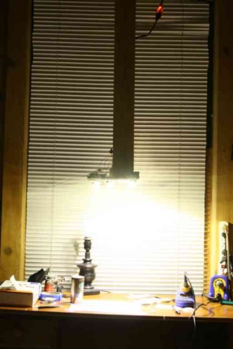
A bit ago I realized I needed to start documenting better and figured a picture was worth a thousand words, so at a 32fps x 1,000, well, in short video documentation should kick-ass (I submit for further evidence chickenparmi’s works :). Well, I got to trying to figure out how I was going to make these videos. That’s when I came up with the idea of a piece of wood hanging from the ceiling–feel free to copy this design, it is open-design.
Well, I attached a board with a hole on it so my iPhone could lie there and take videos of whatever my hands were doing. But I noticed there simply wasn’t enough light in the hacking hours (after the wife’s asleep) to do a proper video. That’s when I began looking into cheap high-powered LEDs. They aren’t too difficult to work with, the items I ended up needing were.
This may seem high, but the heatsink paste was used for many other things; I made 3 other LED track lights, and other LED lighting projectss with it, and I’ve maybe used 5% of the tube. And the PSU has doubled as a work-bench power supply :)
As many other projectss, this one isn’t done. The original plan was to add an array of light-sensors to adjust the light as move my hands around, thereby auto-correcting for light imbalances in the videos. That part isn’t done.
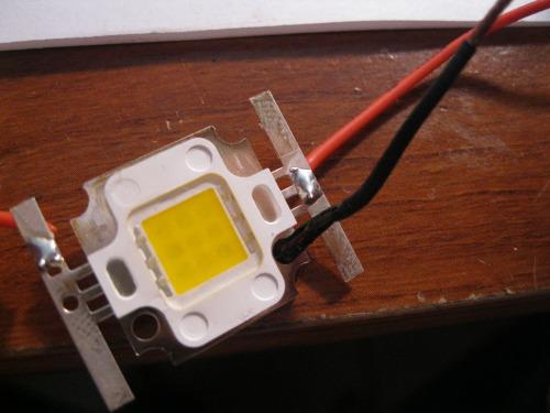
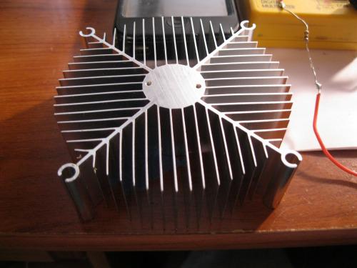
But I jump ahead. When I first started this little projects I had no idea how to work with high-power LEDs. My little ignorant self assumed they were like 20ma LEDs–right? Well, I quickly figured out that heat displacement was the single most important issue. Which is why I ordered a 800 lumen LED 3 weeks before I ordered a heatsink and paste.
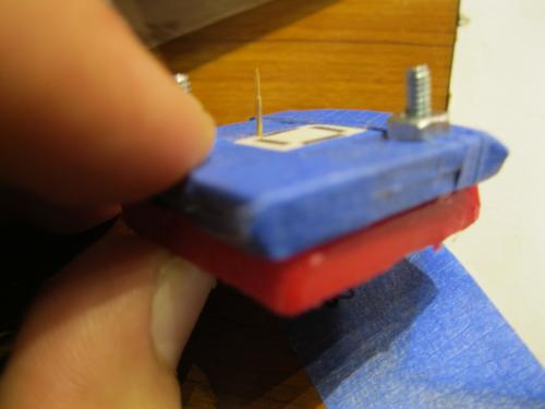
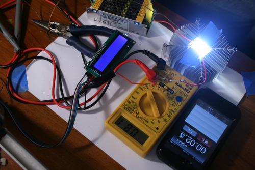
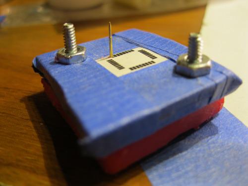
Then, it came to the problem of finding out of my heat sinking was adequate to the massive LED. (I think a 60 watt tungsten produces 800 lume as well? And I know they can cook little cakes–what? It was my sister’s Easy Bake, oven not mine.) I digress, so being dyscalculia I was trying to find out if I was heat-sinking proper without delving into higher math. That’s when I remembered I had my thermocoupler together from the coffee roaster I built. I strung the coupler together with an Arduino and i2c LCD, giving me a pretty accurate and robust temperature sensor.
I looked for a bit, but I couldn’t find the information on the theremal breakdown on the 800lm LED. Eventually, I thought I’d use masking tap to tape the coupler probe against the face of the LED and wire it up (with an appropriate resistor, of course).
The LED was on 1.5 seconds before it blew up to around 180F. Uh, ya, I broke out the heatsink. This time, I attached the LED to the heatsink with a bit of thermal paste. I think attached the two screws, which further pressed the LED against the heatsink. Then, I put coupler probe against the face of the LED. I bit off the last of my finger nails and flipped the LED back on. This time, the temperature sensor went up _much slower_. And after a few minutes stuck around 112F. Of course, I didn’t know if this was beyond the point of thermal breakdown, but I assumed since my own body temperature wasn’t far off, and I wasn’t exploding, then it would probably be ok. I also touched the face of the LED and was able to leave my finger own for longer than 30 seconds. This I’ve found to be the most empirically reliable test. With mounting evidence I decided to cut another hole in my board-from-the-ceiling…thing and attach the light. And there we have it. I’ll report when I’ve added the light-sensor arrays.
XL4432 Breakout – Telemetry is Voodoo
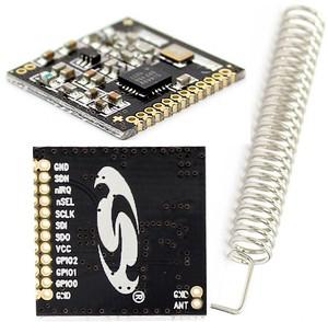
While I was reading about telemetry I discovered these little boards for $3.98 and grew curious if I could do anything with them, other than bricking them. I was very curious about the claim on range, “1000 meters.” Even with the BS de-modifier bringing the range down to around 500 meters, that was still something I would love. So I ordered two and made breakout boards for them.
They came in and right away I had macabre feeling that reminded me of the HM-10 boards. Well, I’ve not played with them enough to know if I’ve killed them. I go pissed off with my logic-level converter slipping and feeding the board with 5v (a cheap jumper wire came loose from the breadboard).
I stopped what I was doing and re-made the breakout board to include a TXB0108 (Digi-Key: $2.30). This is the same little chip that’s in Ada’s 8-Channel Bi-directional logic-level shifter.
That’s really the whole story here, well, except I’ve been trying to find information on hooking these little guys up with Arduinos for when I do get them wired with a voltage translator. I’ve found much thus far, but this seems promising. Sadly, I can’t figure out how he’s got the XL4432 wired up by his poorly drawn schematic(?). Anyone care to give an opinion as to whether those grounds are connected? Logic and CtC both state, “Always, always, connect all grounds.” And if I remember my EE schematic lingo, isn’t dot on connections most often used when there is an extraordinary node?
Oh well.
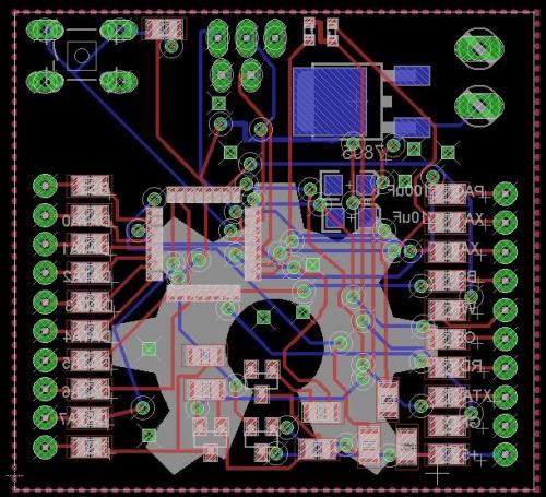
Atmega Fuse Doctor & Pogo Board
I’m not patient. At all. Which lead me to brick a few Atmega boards (1, 2). This upset me, especially since one of those chips was ~$12-17. I had bricked the chips trying to set their fuses in Atmel Studio. Due to the price of these chips I feel it was natural for me to begin looking for a solution. And apparently the Fuse Doctor is one such solution. In essence, it uses the high-voltage programming functions built into Atmel chip.
I thought, “Great. A way to save my chips!” But…I ran into a problem when I saw the board build, it was an etch a home design. And I still do not have pant free of ferric chloride stains. So, I set to re-designing the board into a version I could send off to OSHPark.
I found out the designer had a SMD version of the board ready to go. But, after looking it over I came to the conclusion it would simply be to expensive to print. So, I set out to shrink it.
In the end, I printed a board for around $12. But like the rest of the items here, it didn’t work as expected. The problem had to do with an extra node I missed, which led to a short-circuit around the voltage regulator. So, I just sliced the trace and was able to at least get pulled up in Atmel Studio and the hex file written to the chip. So, in theory, if I can correct short-circuit, supply it with 12vs, and connect it to the Atmel chips, I should be able to restore them.
You might see in this image where I’m providing the board with a pre-regulated 5vs through a via. This was to circumvent the short-circuit around the on-board regulator. Also, I had to attach my AVR wires on the other side of the 1k resistors to get the board signature read in Atmel studio.
Kariloy–who has a complete Fuse Doctor by the way–reminded me that even if I finished my board, I probably shouldn’t hook it directly to the bricked board. Rather, I’d need to attach to the chip directly. Of course, in the original fuse doctor, this was done by a DIP socket. But I don’t use dips… So, I began to think I should just give up on the idea.
Then, I remembered Pogo Pins. I jumped on eBay to see if I could find any pins with a small enough head to fit against a TFQP lead on chips I used. These are the pins I ended up ordering.
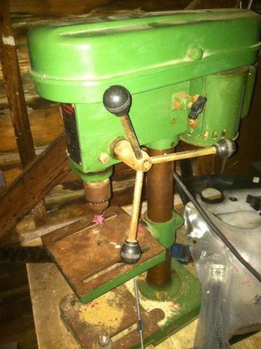
When they came in I was pleased to find they would probably be small enough to fit against a single lead without touching its neighbors. I then started looking for a way to create a jig. I settled on using HDPE (cutting board) I had left-over. I figure I could drill holes in it using the bits I had left over from the Hunter S. Thompson board debacle using OddBot’s old drill-press.
<—– OddBot’s drill press (thank you OddBot ;).
When I got ready to drill the holes, I got into Eagle and printed out the footprint of a 32-TFQP chip. I cut that out and then cut my HDPE to the same size, making two pieces with enough room for the drill guide in the center. I then drilled two holes in adjacent corners from the other. I put a couple of 4-40 screws and nuts to clinch the two pieces of HDPE together. The idea being, I could spacers between them later and slip the pogo pins through the top, solder the wire on its bottom, then let them rest on the bottom piece of HDPE. Not sure why I state all that….the picture I think explains it.
After I had the hole thing screwed, tapped, and clinched, I ran out to OddBot’s drill press, fitted it with the smallest bit I had and tap over one of the pads. I then pulled out one of the small pins and was surprised to find it fit snuggly.
And that’s where I stopped, the main reason was not wanting to have to lookup the pinout for the high-voltage serial programming interface on the Atmega-328-P.
Thermostat
I’m not going to write this up until I do something different then the guy I stole it has done.
My wife, Bek, asked me awhile back to make her a smart thermostat, which I replied, “I’m only at the dumb-thermostat skill-level. Will that do?” She glared, so I Googled for some planes.
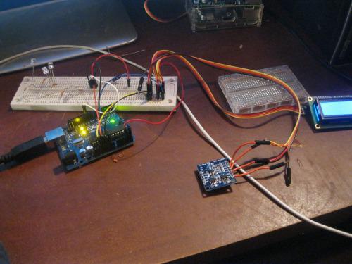
I found this guy’s Arduino thermostat and I realized I had most of the parts already lying about.
– Arduino Uno
– I2C Real Time Clock
– I2C LCD
– Seeed Relay Shield
– Dallas 1-wire Temperature (DS18B20)
The idea is pretty simple, the voltage line is tied together on all the legs of the relay shield and the Arduino connects to it. The Arduino reads the temperature from the sensor, checks the time on the I2C RTC, and prints both to the I2C LCD. Also, if the time is correct (after 4:00 PM) it will automatically kick on the AC. I’ve got it all together and working, just not tied to the AC lines. I was trying to find a way to power it, since all the AC lines are 24v and there is no ground. So, I bought:
Which gives me 15v, 6A unregulated, or 4.5-40v at 1.6a.
Now, looking back, this projects is more expensive than buying a smart thermostat, and I don’t recommend it. The main reason I went with this build was because I owned everything but the temperature sensor and PSU.
Distcc and Gstreamer on Raspberry Pi:
When I began playing with the OpenCV I fell in love. I just felt it has so much to offer us, but I had really kept my tinkering limited to what could be done on the Raspberry Pi. When I finished the little face tracker on the Pi, I knew it would work well as a sensor, but would not approach the level of function I wanted. In short, the Pi simply could not give me the speed I needed. I pulled up OpenCV on my desktop (I wont go into the specifications, just know it’s faster than the Pi) and realized pretty quick I’d need to send the video data from the Pi to the desktop if I was to get the results I wanted.
So, I began playing with cheap ways to send video data to the desktop. I started by attempting to use Gstreamer to pipe the video data from the Pi, over my WiFi, into OpenCV on the desktop. Twenty hours later…I realized I was too dumb to make this happen. I began reading.
Put simply, there are so many compatibility issues with this process. I still think it is possible, I just got worn out trying to figure it out. And as I understand it, not all of Gstreamer’s development plugins work on the Pi. Then, it was a question of what was going to capture the video (Motion, FFMPEG, etc), and whether one, if any, of these programs liked to play with OpenCV, not to mention, a video pipe that came from the Raspberry Pi. There is no need to say, but I’m going to anyways, it was a mess.
I’ve built Gstreamer and FFMPEG on the Pi more times than I can count (not many, I count to like 5). This got me to thinking, “This would probably go faster if I could compile these beefy programs on the desktop. After doing a bit of digging through cross-compiling literature, I decided on Distcc. It seems pretty nifty. It is a genuine remote compiler, meaning there are no SD card swapping and mounting, unmounting. Getting it to run on the Pi was the trick.
I won’t go through all my wasted time and effort to sort out how to setup Distcc; and, like the other projectss described here, I’m still not done. Though, this guy’s post has helped me a lot. I’ve learned a lot about Bash scripting and have written a script to setup Distcc, mind you, this script doesn’t work yet, it’s like the rest of the post, incomplete:
I’m embarressed to say how much time I spent fiddling with trying to get Distcc to work properly on the Pi. And so much time wasted was my fault. In the end, it was the manualthat saved me.
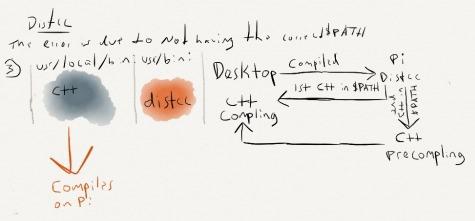
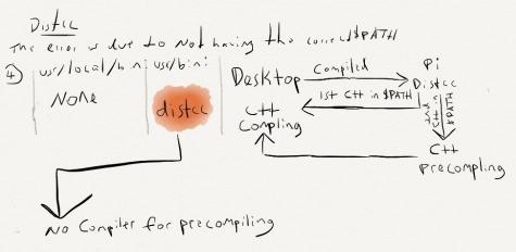
Because I didn’t really understand the symlink in this scenario I was having a hard time figuring out how Distcc calls the correct compiler. From what I inferred, a symlink was created to replace gcc, c++, cpp, cc, g++. Then, when any of these were called, the symlink would redirect the data to the remote compiler on the desktop. So, when during first go I had at installing Distcc didn’t work because the $PATH variable was incorrect, I thought, “Well, if it’s creating a symlink to another compiler, I should just delete the local compilers on the Pi–they’re not needed anyway. That way I’m sure I’ll get the remote.” Due to this stinky logic I issued this command
mv local.compilers localcompilers.old
Sadly, it wasn’t until I read the manual (hey, it’s a long damn manual) did I discover that a “local pre-compiler is used before the data is sent to the remote compiler.” Meaning, every time I disabled the local compiler I done-broke-it.
If the symlink to Distcc comes up first in the $PATH, it calls it as the pre-compiler, then removes it from the $PATH variable. Distcc then calls the the next compiler in the $PATH variable, this time, to it should be the remote compiler.
Given I removed the local, the first compiler it would find it treated as the precompiler, then removed it, leaving no compiler to do the real compiling.
This caused me to get errors stating there was no compiler found.
I discovered all this waiting on one of my clients to finish a mental-health screening. It definitely confused him when I hit my head against the wall and said, “Son-of-a…”
I’d been digging around in the manual on my phone.
To sum up, I know now that both the real compiler and the symlink to distcc must be in the $PATH variable, they just have to be in the correct order.
But as all the tales of woe here, it is unfinished.
UPDATE: I discovered the link I had was referring (which is the true stock image) is unuseable unless update and upgrade are run. Sadly, you can’t do that with a 2gb image. Regardless, I’ve switched the image to the updated (as of writing this) Angstrom image. Please double check and make sure you’ve got the latest image:
Replace the paths in steps 8 & 10 (but I’ll try to keep it up to date). Again, it is unfortunate but you need a 4gb or greater microSD to use these instructions.
**MAIN: **
As I stated, I killed my stock Angstrom on the Beaglebone Black (B^3).
I pieced together how to restore it.
You’ll need your B^3, microSD card, and Ethernet connection.
(WiFi dongle can replace the Ethernet, if you got it working before I did. And if you did, where’s the walkthrough :P?)
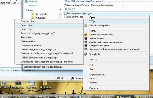
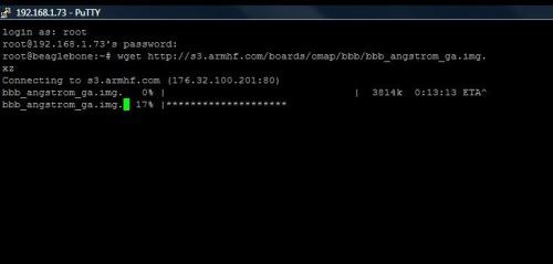
9. Write the Angstrom Stock img to your Beaglebone Black eMMC.
This next step is going to write the image file to your Beagle’s eMMC.
Two notes, it is going to take awhile, if you are curious if it is still installing, use the LED activity lights to guide you. When the PuTTY window gives you back to the command prompt and the LEDs are slowed, you’re good to go to the next step. Oh, second note. Try not to power down the Beagle during this step.
11. Remove the microSD and power back on the Beagle. It should now boot like you bought it (unless, of course, I screwed up. Feel free to yell at me and I’ll fix these instructions).
If you followed this process you’ll see these instructions can be used to write any image file to the eMMC. Let me know if you get a different distro working (consistenly).
Now, I’m going to turn to getting Arch Linux going. Unless, someone else has it working…JerZ? :)
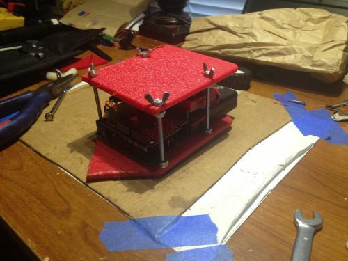
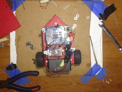 In the end, I really didn’t do anything fancy, as apparent. I drilled holes into the battery plastic-case, that aligned with holes in the robot base, and bolted it together. I, for the first time, used the mounting holes in the Arduino Uno, bolting it to the base. I then “designed” a hood (bonnet) for the little guy. from match HDPE, making sure to bolt it down as well. Lastly, I sealed the motor-gears with electrical tape and put a few drops of oil in them. I noticed this regarding geared mini-motors, they collect hair and will strip out the gears.
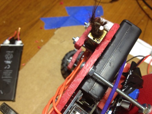
 I was careful not to wrap too much of the motor, since I had the thought it might decrease thermal exchange.

 Like I said, I didn’t regret the 0402s at all. They all soldered on pretty easy. Though, I think my primary beef with 0402s over 0802 is when it comes to tweezerless soldering. See, when I go to solder 0802s I have this process of tapping one pad with a bit of solder, and taking a resistor for example, hold the 0802’s body with tweezers in my left hand while my right hand keeps the solder warm. Then, I simply run one end of the resistor into the pool of solder, move the iron away, then, when the solder cools, let go with the tweezers. To get the other end, I’ll put the tweezers down and simply tap the other end with solder. Voila.
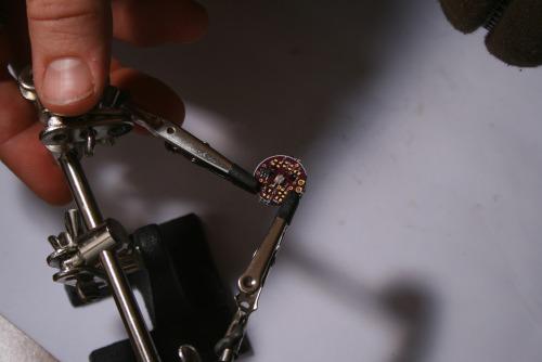 A few notes:
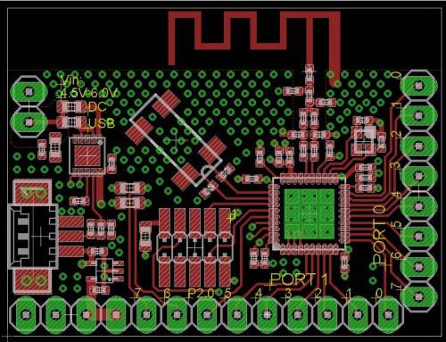
 This realization on top of all the 0402s and the DFN package, well, I decided I wanted to play with the chip on a completed board, with already installed firmware before I sunk time into a personal development (fancy words for: I got lazy).
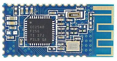 They aren’t bad little boards. But, they were little. I tried soldering on jumpers to the ant sized grooves, it didn’t go well. I knew to really start playing with the board I needed a breakout.
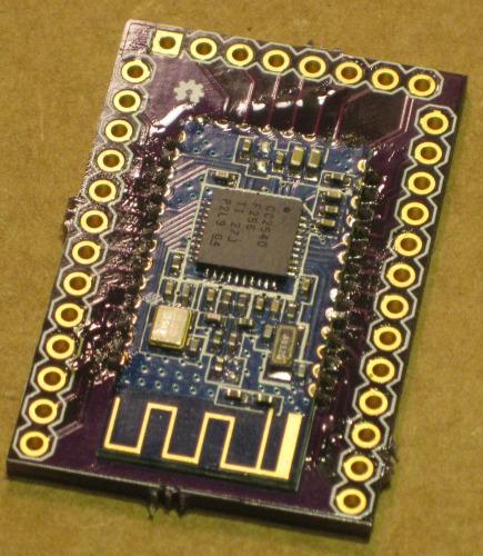
 The manual answered a lot of my questions. It came with a complete pinout (even a schematic!). After playing with the commands I was re-naming the module, resetting it and running many other needed commands.
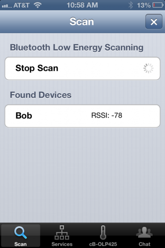
 So, no chance on getting older firmware. I started preparing to implement my Atmega & HM-10 team. I strung up the HM-10 on the backpack breadboard of Silas’ bot (my son’s bot).
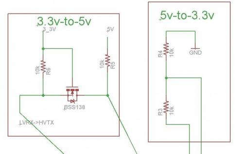
 I’m not going to write this up until I do something different then the guy I stole it has done.
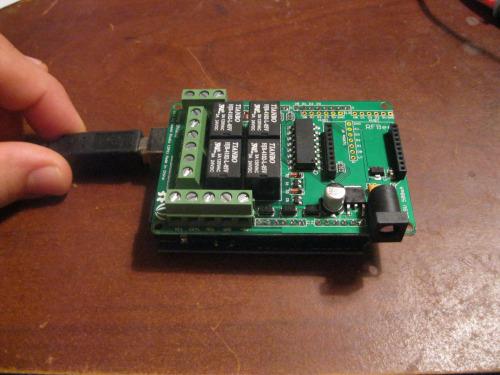
 I discovered all this waiting on one of my clients to finish a mental-health screening. It definitely confused him when I hit my head against the wall and said, “Son-of-a…”