LPC1114 -- GCC Toolchain Setup

Originally posted on www.letsmakerobots.com

UPDATE: I tweaked the source and rebuilt lpc21isp to allow for automatic mode switching, bootloader and program, from an FTDI breakout.

A few months ago Bdk6 sent me an LPC1114 ARM processor. Not going to lie, I had little idea how to use the chip.

Bdk6 and his kids had created the Valdez family with the chip:

I tried several IDEs to get the chip going. I wasn’t happy with any of them.

LPCXpresso was confusing and intimidating. Since I was trying to learn the chip and a new IDE. Add to this, NXP didn’t have libraries for the chip, so I was trying to integrate the LPC1114 CodeBase libraries. They appeared to be incomplete and unkept. It didn’t matter, I couldn’t seem to integrate the libraries into LPCExpresso.

I then started using Mbed. A lot more luck there. But it was uncomfortable. I’m betting most reading are familiar with Mbed, therefore, I won’t go into the usual rants about it being webbased and closed-source.

There are other problems with Mbed.

First, it is not a complete development solution. You need a flashing tool to upload code to the LPC1114 chip. The easiest tool to use is FlashMagic, which gives you a nice GUI to interact with the LPC1114. There is a slight problem, Mbed produces a .bin file and the LPC1114 needs a .hex file, subsequently, FlashMagic only allows uploading of .hex files. So, you have to use a third tool to convert the file from .bin to .hex before uploading. Sigh. It’s a lot of trouble.

Anyway, I eventually got it to blink a light

Video

I craved more freedom, so I started looking for tools that’d allow me to code for the LPC1114 freely. A bare-metal solution. Just me, a compiler, and the LPC1114 User Manual (datasheet). Luckily, most of the work had been done for me. Frank Duignan, Ted Burke, and Bdk6 had pretty much all the answers pre-compiled for my little brain. Here’s the steps I used to get a command-line programming environment setup.

1. Download and install GNU Tools for ARM Embedded Processors (Win32 Release – 2013, quarter 3).During the installation, make sure to check the box “Add path to environment variable.”

Check “Add environment variable.”

If you missed this part, you can add a path to the environment variables by:

Right clicking on This PC / My Computer –> Properties –> Advanced system settings –> Environment Variables –> Select “Path” under “System Variables –> Edit. Go to the end of the list of paths, add a semicolon, then place the path of the GNU tools bin.

For me, this was “C:\Program Files (x86)\GNU Tools ARM Embedded\4.7 2013q3\bin

We are going to add several paths to the path systems variables. So, refer back to these steps as needed.

2. Download Frank Duignan’s Windows linker script, LPC1114 header file, and build batch file.

Duignan’s LPC1114 tools

Ted Burke was nice enough to put these up for us. However, there’s two pieces missing for us to use these amazing tools.

3. Create a workspace folder. e.g., “C:\Users\Ladvien\Documents\LPC1114_Bare_Metal”.

4. Install binutils for file conversion. Binutils has to be compiled for Windows, though, I was able to find them pre-compiled.

Download Binutils compiled for Windows

Really, we are only using Binutils for objcopy, which is at the end of the batch file. This translates the .elf produced by the ARM compiler into a .hex file. To unzip Binutils file I’d recommend using 7zip. After installing them add the bin folder to your environment variable (see step 1). For me, I added “C:\Users\Ladvien\Documents\LPC1114_Bare_Metal\Ming32\bin”.

5. Create a build script in a batch file.

Create a build batch file recommend by Duignan and Burke. Open your workspace folder, create a new text file, enter the following:

arm-none-eabi-gcc -mcpu=0 -mthumb -v -g -c init.c -o init.o
arm-none-eabi-gcc -mcpu=0 -mthumb -v -g -c main.c -o main.o
arm-none-eabi-ld init.o main.o -v -L "C:\Program Files (x86)\GNU Tools ARM Embedded\4.7 2013q3\lib\gcc\arm-none-eabi\4.7.4\armv6-m" -lgcc -T linker_script.ld --cref -Map main.map -nostartfiles -o main.elf
objcopy -O ihex main.elf main.hex

Save the text file in your workspace as “build.bat” Be sure to include the quotation marks, since this will convert the file from a text file to a batch file. This is the same build commands put together by Duignan, but I’ve added the “-v” option. This is the verbose mode and will spit out an errors during compiling.

6. Setup a C++ friendly text editor, like Programmer’s Notepad.

7. Create a file called main.c in your workspace directory. Enter the following text:

/* Simple PWM demonstrator program
 * The program simply ramps the duty of pin 10
 * from 0% to 100%  and then resets back to 0%
 *
 */

#include "lpc111x.h"

void ConfigPins()
{
	SYSAHBCLKCTRL |= BIT6 + BIT16; // Turn on clock for GPIO and IOCON

	// Begin Port 0 setup.
	// Make Port 0 bit 5 behave as a generic output port (open drain)
	IOCON_PIO0_5 |= BIT8;
	// Make Port 0 bit 10 behave as a generic I/O port
	IOCON_SWCLK_PIO0_10  = 1;
	// Make Port 0 bit 11 behave as a generic I/O port
	IOCON_R_PIO0_11  = 1;
	// End Port 0 setup.


	// Make pin 10 behave as a PWM output CT32B1_MAT0
	IOCON_R_PIO1_1 |= BIT1 + BIT0;
}
void initPWM()
{
	// will use counter/timer CT32B1
	// Turn on CT32B1
	SYSAHBCLKCTRL |= BIT10;
	// Use match register 3 as period register because its output
	// is not pinned out.  A value of 48000000 produces a frequency of 1Hz
	// so, to generate a 30kHz pwm signal, set MR3 = 48000000/30000 = 1600
	TMR32B1MR3 = 1600;
	TMR32B1MR0 = 1600; // Zero output to begin with
	TMR32B1MCR = BIT10; // Reset TC on match with MR3
	TMR32B1TC = 0 ; // Zero the counter to begin with
	TMR32B1PWMC = BIT0; // Enable PWM on channel 0
	TMR32B1TCR = 1; // Enable the timer

}
void setDuty(int Duty)
{
	// sets the duty to the percent specified.
	// Need to 'invert' the requested duty as the PWM mechanism
	// resets the output at the start of each PWM cycle and then
	// sets it on match.
	TMR32B1MR0 = (100-Duty) << 4;
}
void delay(int dly)
{
	while(dly--);
}
int main()
{
	int Duty=50;
	ConfigPins();
	initPWM();
	while(1)
	{
		setDuty(Duty++);
		if (Duty > 100){
			for (Duty > 1; Duty--;){
				setDuty(Duty);
				delay(100000);
			}
		}
		delay(100000);
	}
}

Save the main.c file.

I’ve modified the above code from Duignan’s to make it comparable to the Fade sketch in the Arduino examples.

8. Open the command prompt in your workspace directory. Run your build.bat file.

**

**

After running the build.bat, it should build five files: **main.o, int.o, main.map, main.elf, main.hex. **If it doesn’t build correctly, double check the path variables for both the compiler and binutils.

We still have the problem of getting the main.hex uploaded to the LPC1114. You can use FlashMagic, like above, but I’m trying to stick to the command line, that’s where lpc21isp comes in.

I’ve pre-built lpc21isp for Windows.

Download LPC21ISP (now with automatic mode switching! :)

But if this doesn’t work for you, then you’ll have to build it yourself.

10. Create a another batch file called,LPC1114_upload.bat

Only one line this time:

lpc21isp -wipe -localecho -hex main.hex COM3 57600 12000

You’ll have to adjust the COM port to the port you are using. Here is a little bit of a** guide using lpc21isp**. Also, you’ll either need to put the lpc21isp file in one of the folders added in the path variable. Or, make sure the LPC1114_upload.bat and lpc21isp files are in the same directory as your main.hex.

11. Wire up your LPC1114.

One last bit I should point out, when “DP24” is connected to ground and then voltage is supplied to the LPC1114, it’ll enter the hardware bootloader. But, if DP24 is open or (preferably) pulled-up with a resistor when voltage is supplied to the LPC1114 then it’ll run whatever code has been uploaded to the flash memory.

“DP24” is actually pin 1 on port 0.

12. Connect your LPC1114’s RX/TX to an serial connector, put it into the bootloader mode by connecting DP24 to ground, then apply power to the LPC1114. Lastly, run the LPC1114_upload.bat file. This should result in the LED connected to “SWDIO” pin to fade on and off.

And that’s what I’ve got. I’m going to start working on coding now, so I’ll trade to add to this write-up as I’ve more to share. I plan to try these steps on my lab machine around June 1st to make sure they work. But if anyone uses them before them, please let me know if there are corrections to be made. As always, I value feedback and critique.

Update: FTDI Mode switching

The lpc21isp allows for automatic mode switching, that is, you can use an FTDI cable as below:

Then replace the line in your LPC1114_upload.bat file with

lpc21isp -wipe -localecho -control -hex main.hex COM3 57600 12000

This will automatically put the LPC1114 into program mode, upload your code, then reset to run your newly uploaded program. Just like Arduino! (Bdk6, you didn’t see that statement, right? :)

Of course, lpc21isp is an agglomeration and had an error(?) that wouldn’t reset the chip after downloading the new code. I simply commented an if-statement and it is now “working.” I’m sure I’ve lost some robustness, but hell, it does what I want with no apparent side-effects. If you would like to know more about how I “broke” lpc21isp check my Github readme on the issue.

Kossel Mini Calibration

This is a continuation of my Robot Metallurgy 101 – AVR Lesson Journal

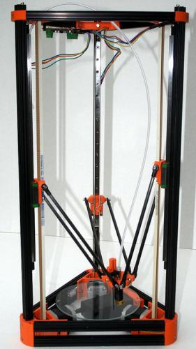
This is the second part of my Kossel Mini build log

When I made my mind up to build a 3D Printer I knew I was in for a ride. I knew I was going to spend an insane amount of time calibrating the damned thing. Well, my overestimation was nowhere near the truth. I’ve spent literally days calibrating this damned machine. Mind you, a lot of it was because I refused to “RTFM.” But the other part was because there doesn’t to seem to be a manual on calibrating the Kossel Mini. Therefore, I’m going to attempt to present what I’ve learned for delta printer posterity.

Note, this guide will focus on the “holes” other sources of documentation have, more specifically, holes in:

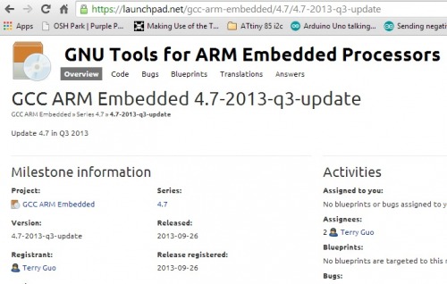
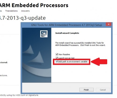
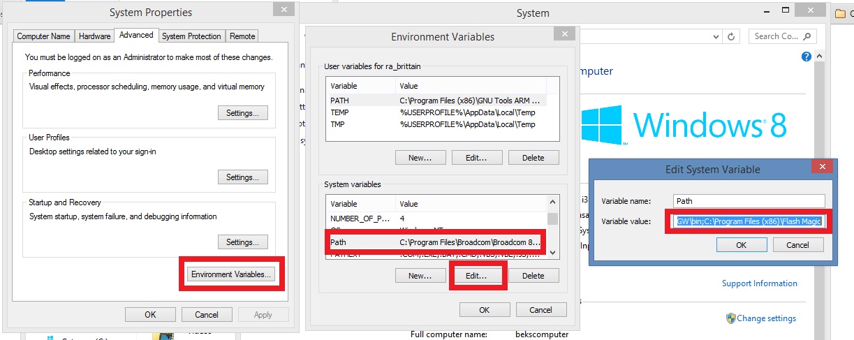
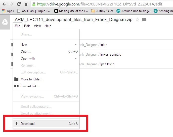
Let’s start with getting the firmware and software.

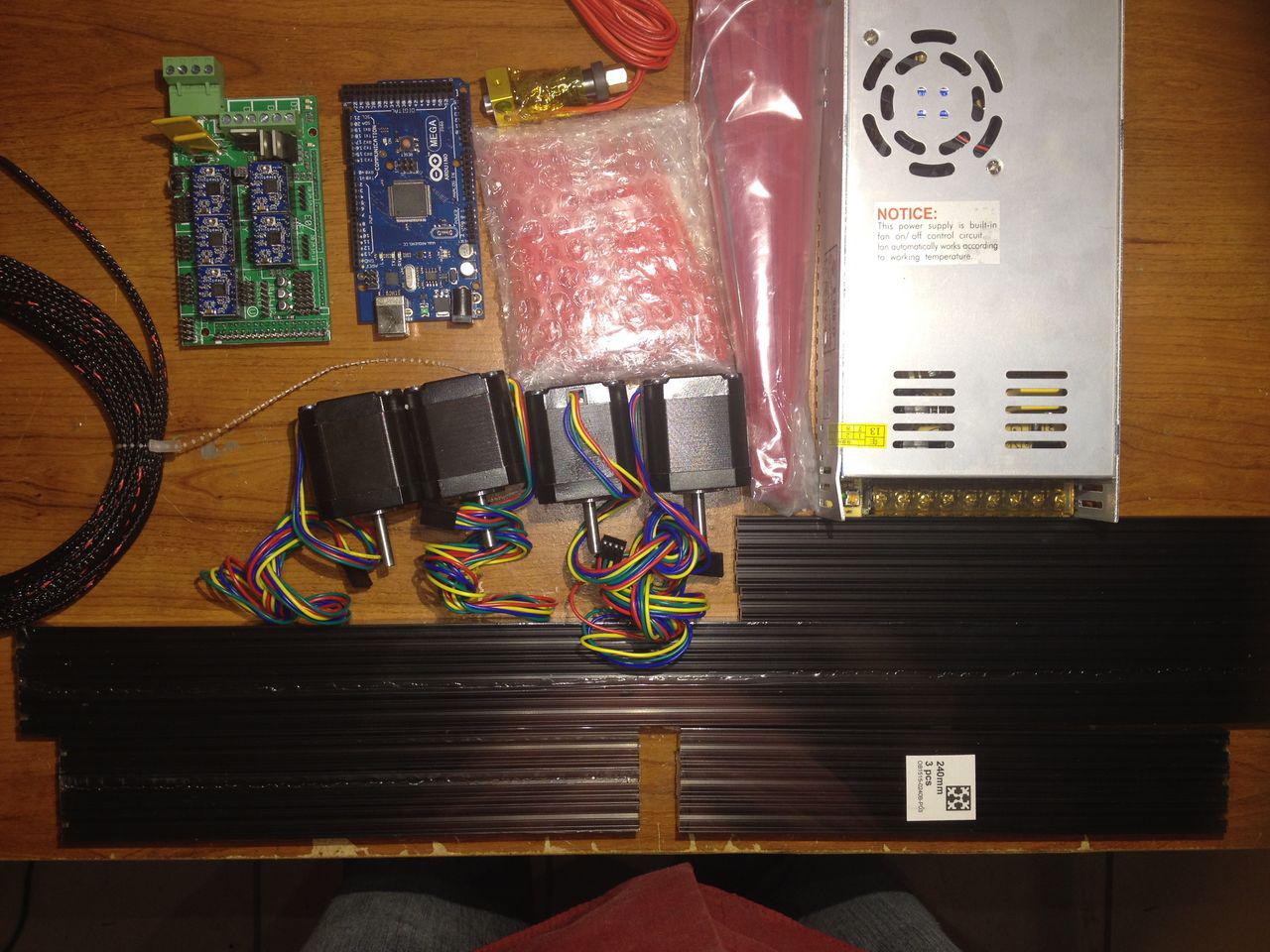
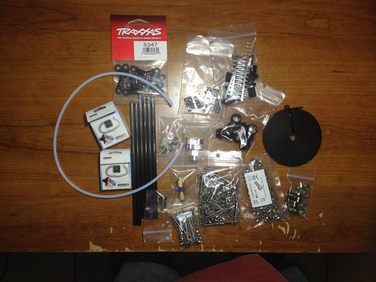
I mentioned in the physical build of my printer, I bought most of my stuff as a kit from builda3dprinter.eu. I’ve been pleased with the kit. Most of my frustration with the physical build was me not understanding how the pieces work together (for instance, the auto-probe). Anyway, Ardon Camp from B3DP has provided some starting firmware for his kits, which is listed on his “Initial set-up” page

  1. Marlin Arduino firmware for B3DP Kossel Mini kit
  2. Pronterface
  3. KISSlicer

As of now, I switched Proterface out with Repetier and KISSlicer with Slic3r.

  1. Repetier
  2. Slic3r

We should have firmware (Marlin) and a host (Repetier or Pronterface). What now?

Well, hind-sight is 20/20, so here are my suggestions.

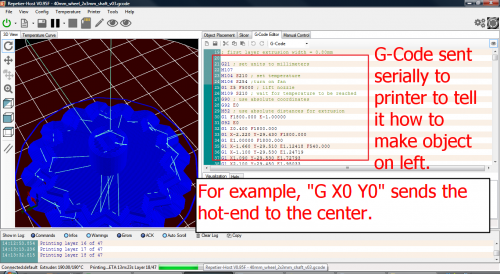
1. Get familiar with G-Code

Most 3D printer firmware operates on a standard set of instructions called G-Code, which are sent to the printer via serial connection. There is a code for everything, turning the heater on, going to an end-stop, writting settings to the EEPROM. My recommendation, before you start moving any part of your printer, read through all the G-Codes. This will give you an idea how your software talks to the printer.

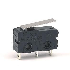
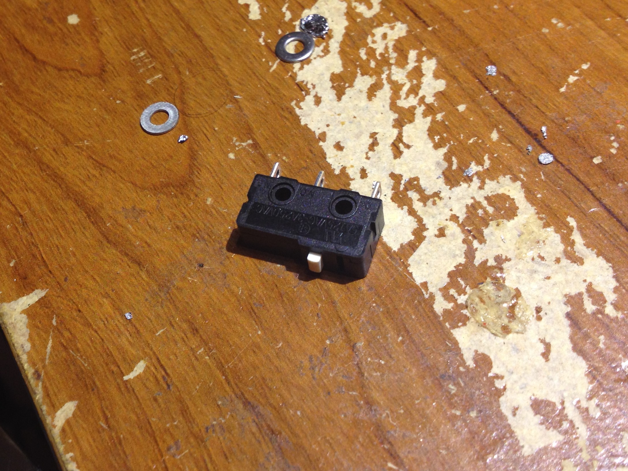
2. Check, re-check End-Stops connection before testing motors

Now that we’ve read up on G-Code, we know the code to check and see if the End-stops are triggered is M119. Check this a few times before you attempt moving anything electronically. If everything is connected correctly it should look like this,

No Buttons Pressed:

  1. Y_MAX: Open
  2. X_MAX: Open
  3. Z_Min: Triggered
  4. Z_Max: Open

All Buttons Pressed:

  1. Y_MAX: Triggered
  2. X_MAX: Triggered
  3. Z_Min: Open
  4. Z_Max: Triggered

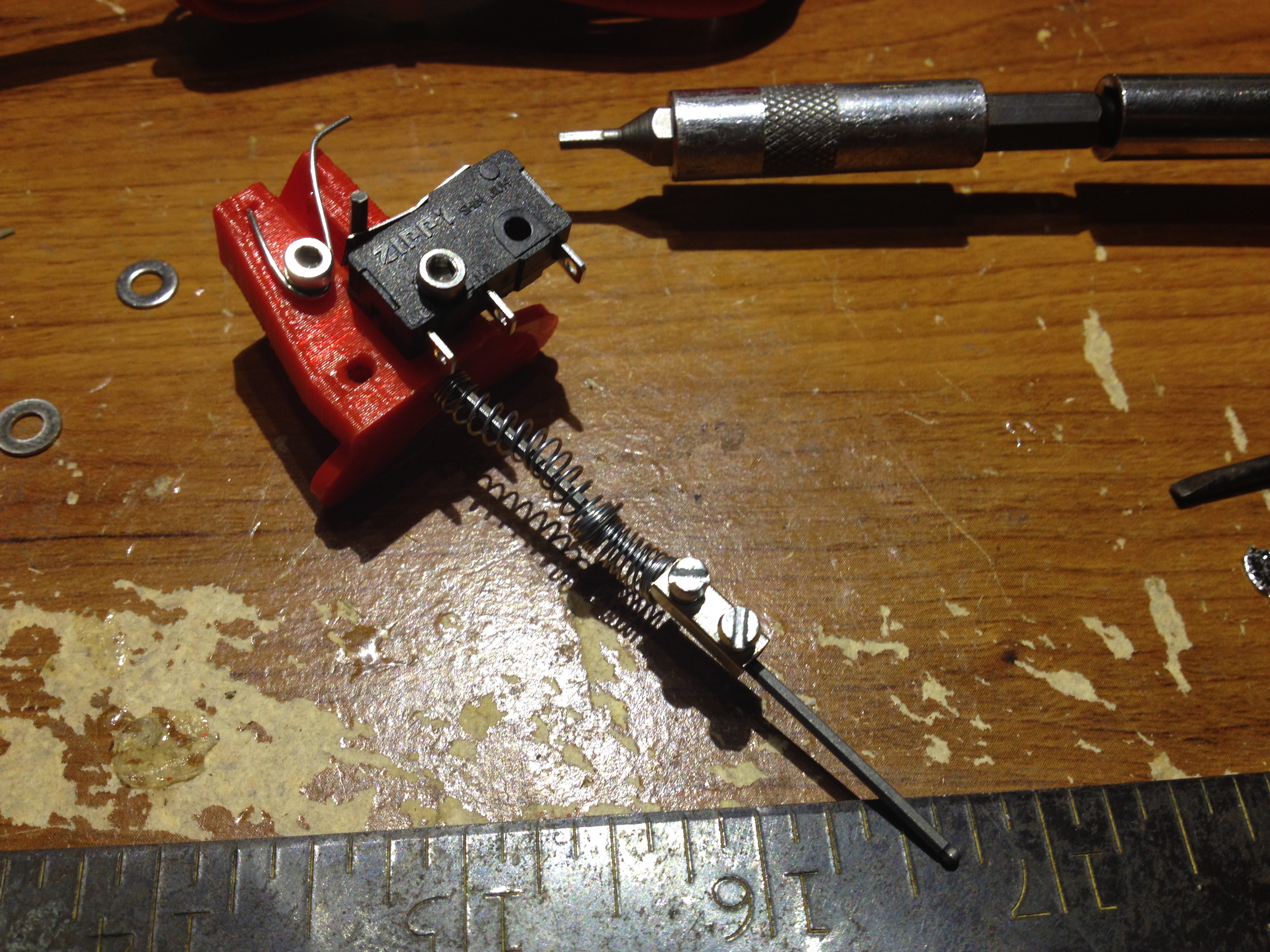
It is important to have these trigger correctly, otherwise, your hot-end will go crashing into something. For example, if one the end-stops isn’t triggering then the connected carriage will continue trying to pull past the end-stop, which will result in the your belt-link coming apart.

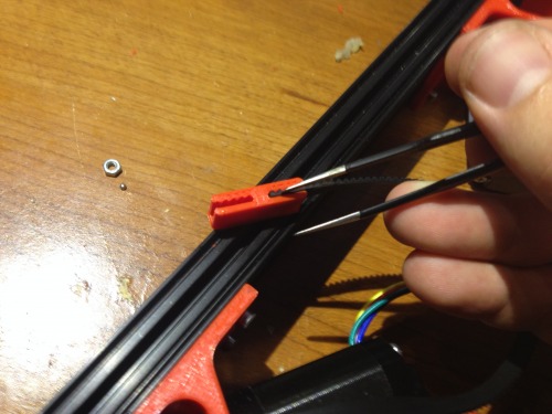
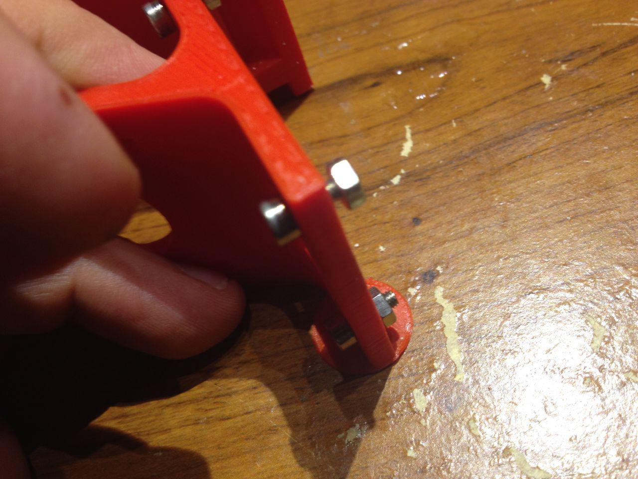
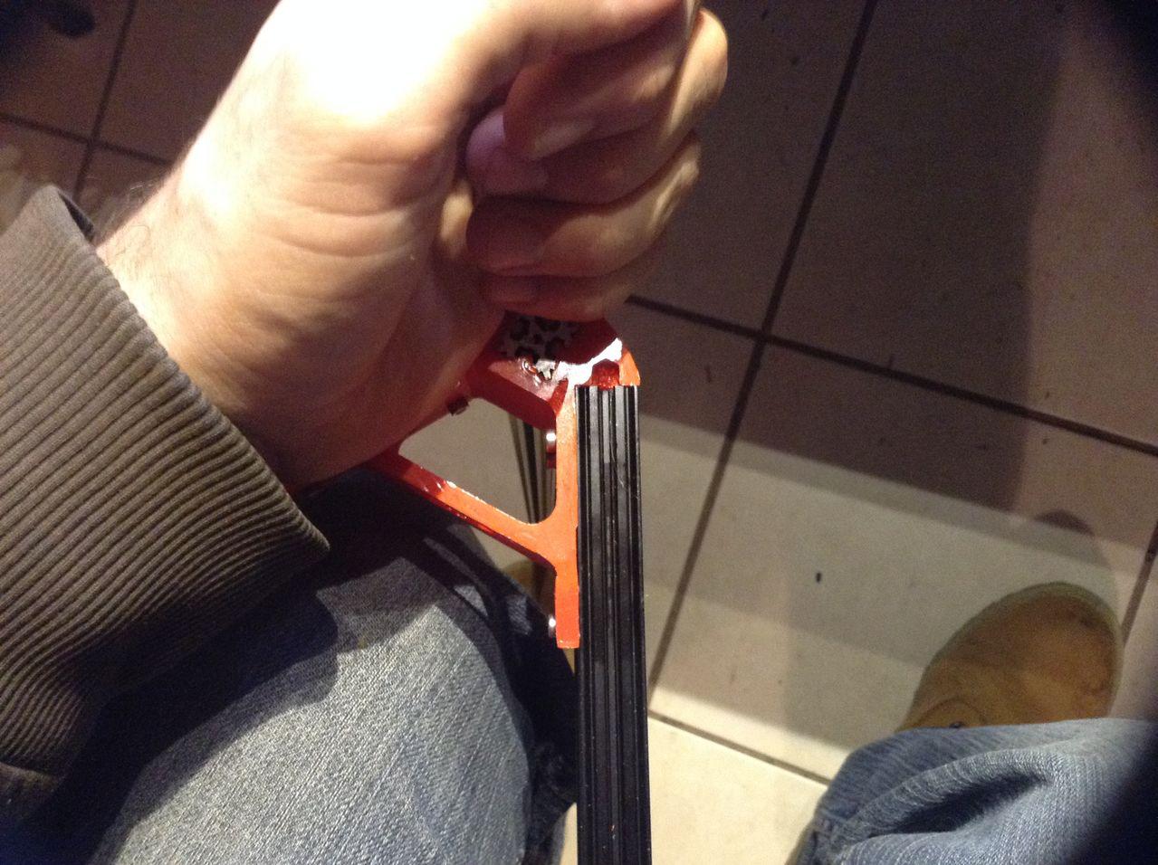
Expect for your links to come apart a few times as you make adjustments.

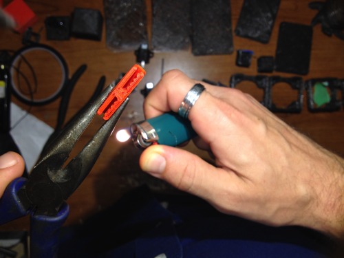
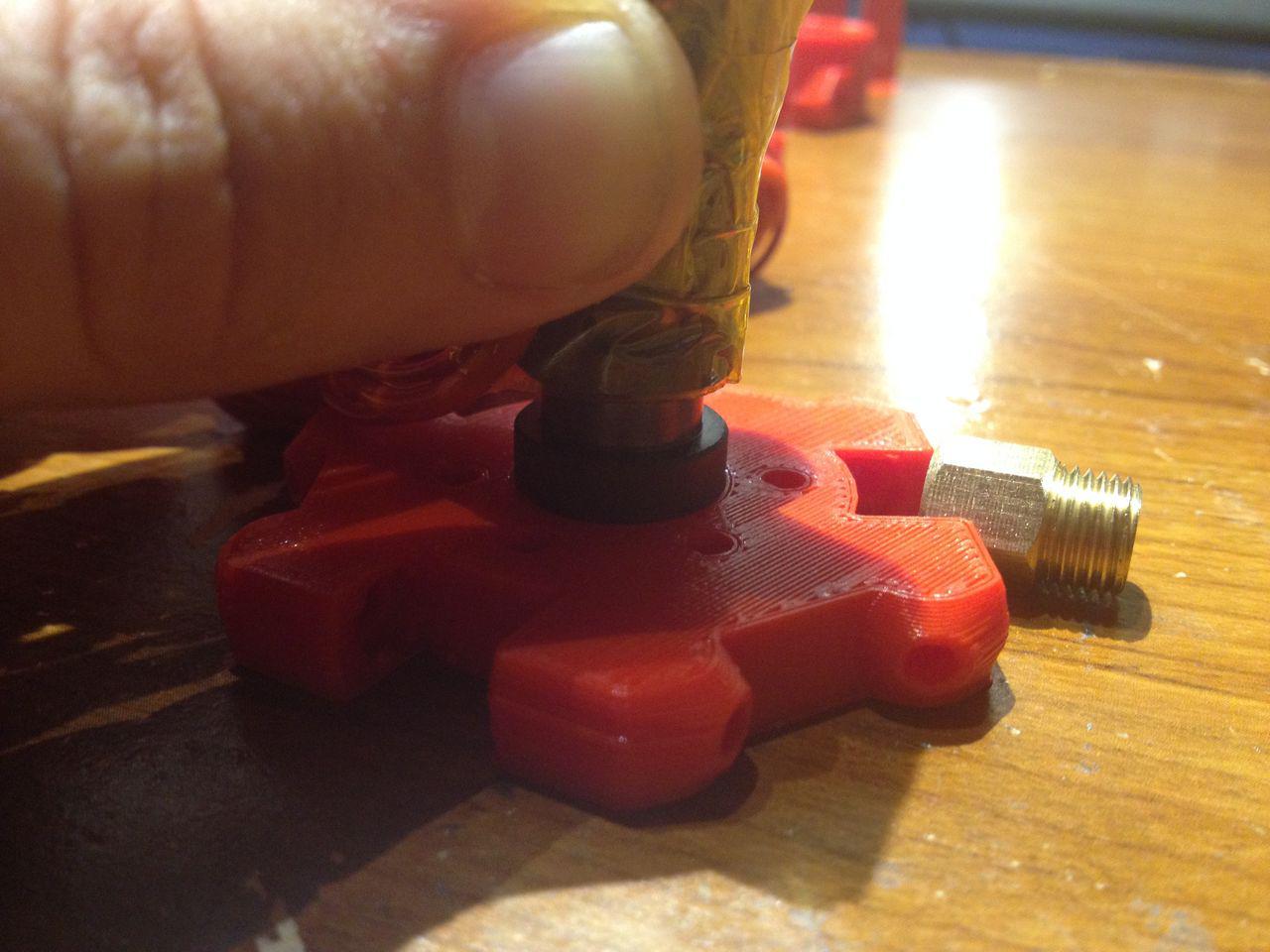
Being forthright and humble, I made so many mistakes calibrating my Kossel that my links began to stretch out and were unable to hold the belt properly.

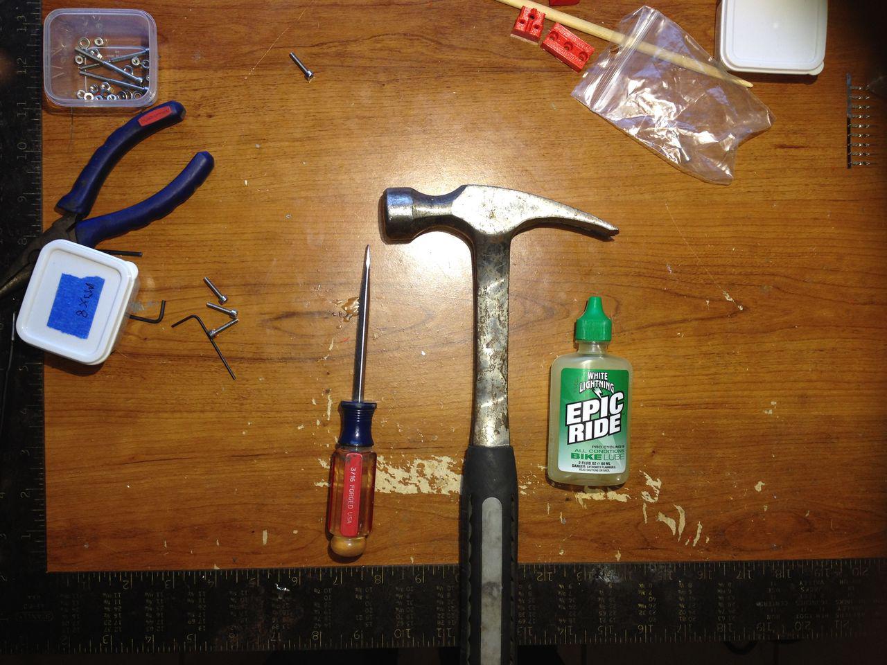
I was able to bend them back into place by clamping them with pliers while heating the bottom side with a lighter.

3. Fans

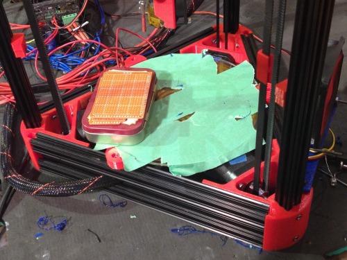
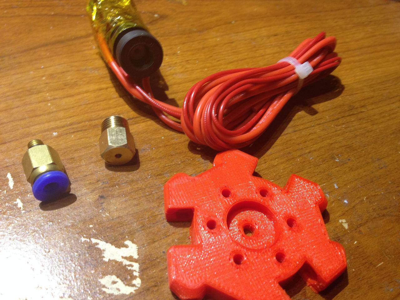
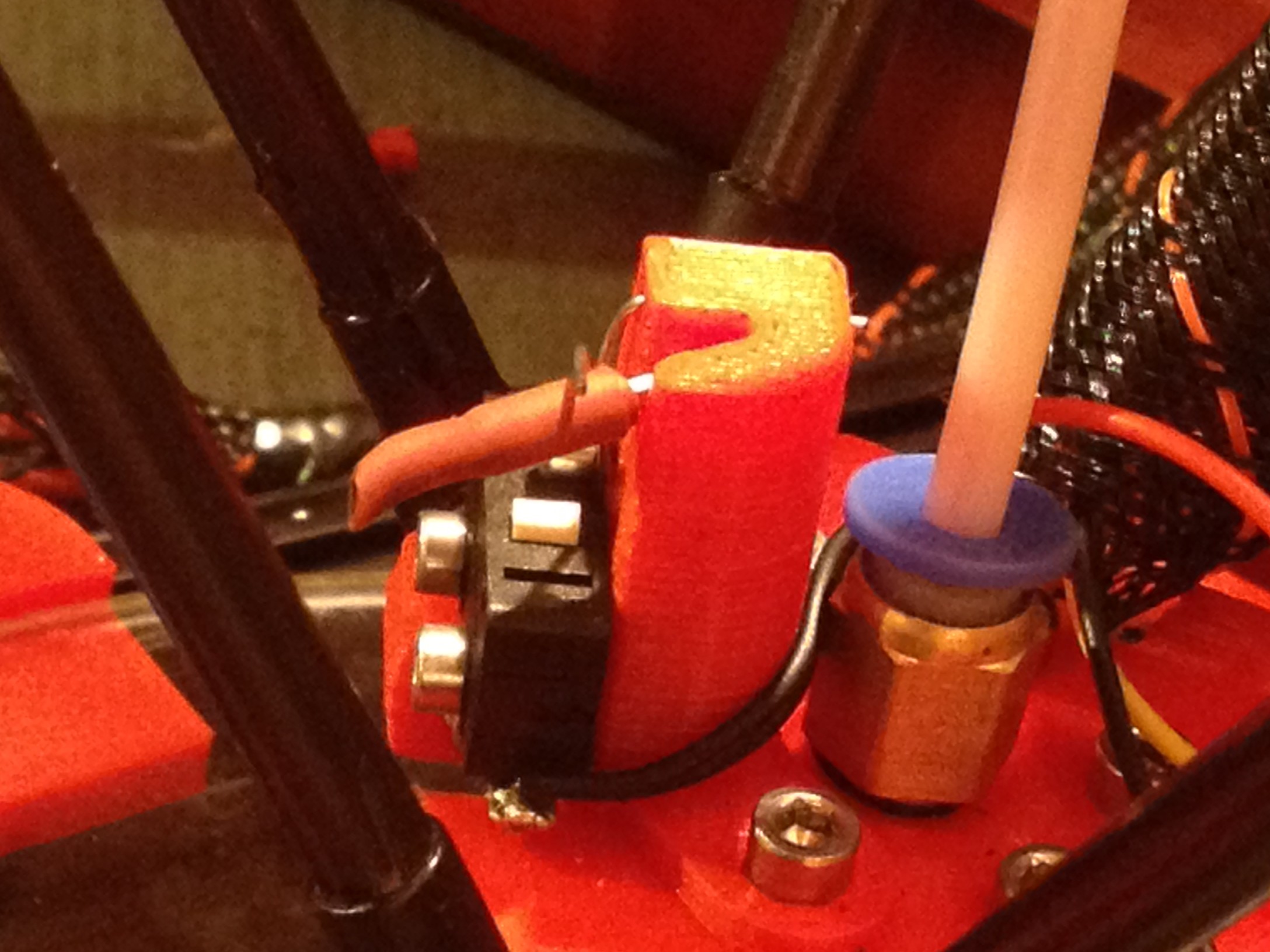
The Kossel Mini has a small 40x40mm fan that blows directly on the hot-end, all the time.

This is required because the hot-end holder is actually a printed part, meaning it is plastic, therefore, if the hot-end exterior isn’t constantly cooled, it will melt the holder and come crashing down on your print plate in a neat heap of defeat.

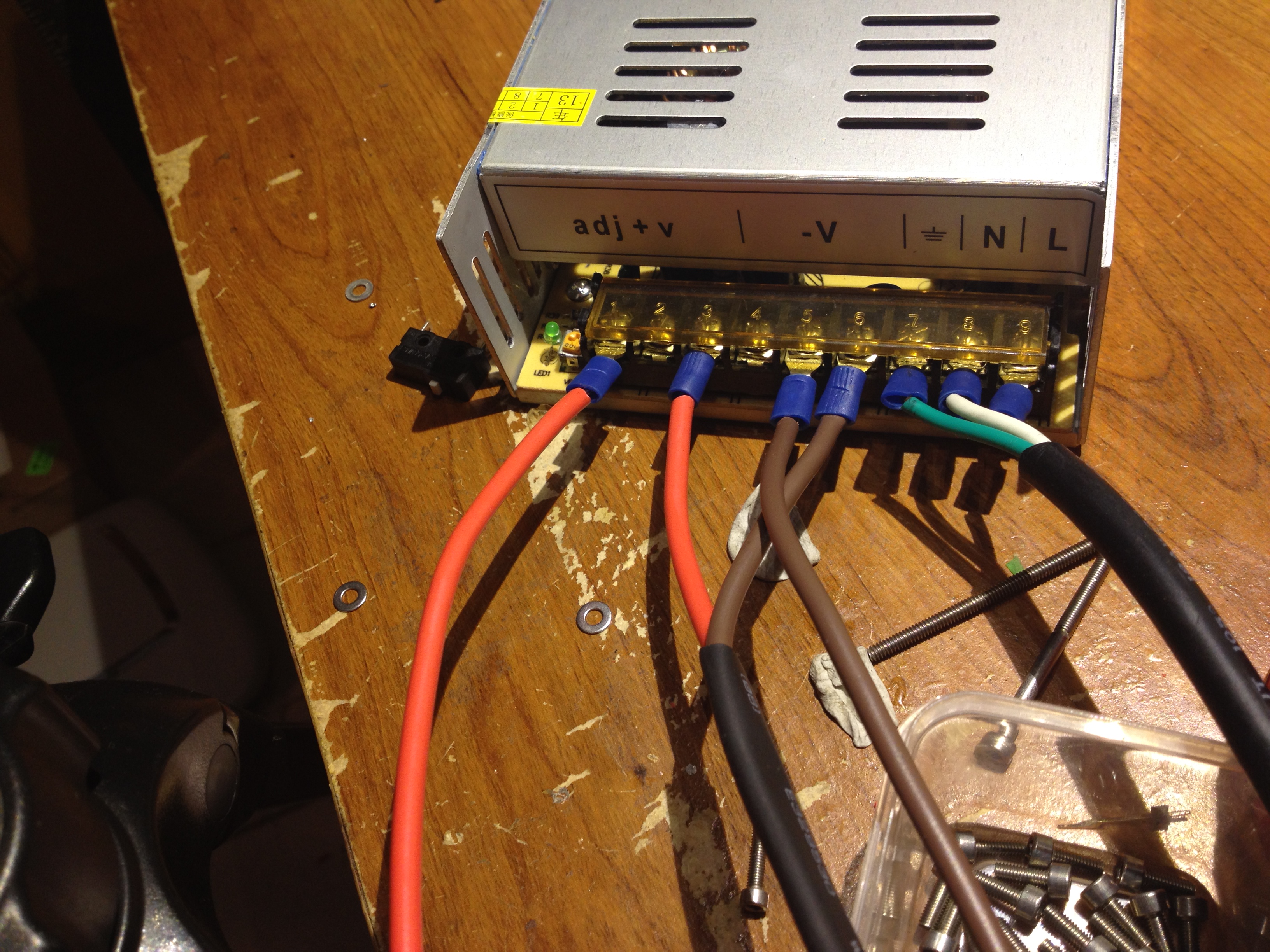
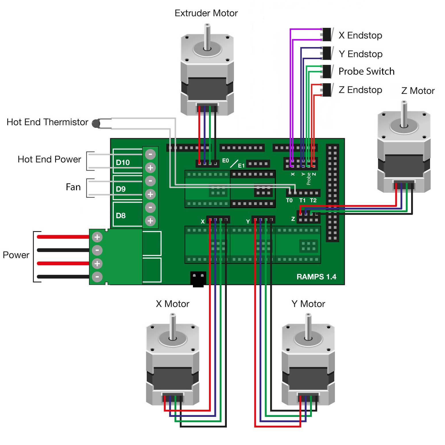
The fan should operate on 12V. You have several options.You can tie the fan into the PSU itself, which would cause the fan to be on everytime the printer is on. Or, you can tie the fan into the Ramps board.

I chose the Ramps. Don’t ask me, probably because I intuitively find a way to do something through hardest means possible.

Anyway, here is how I have all my fans, (1) on the hotend, (2) cooling my extruder stepper, (3) an 80mm cooling the print bed.

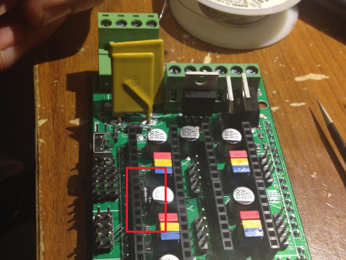
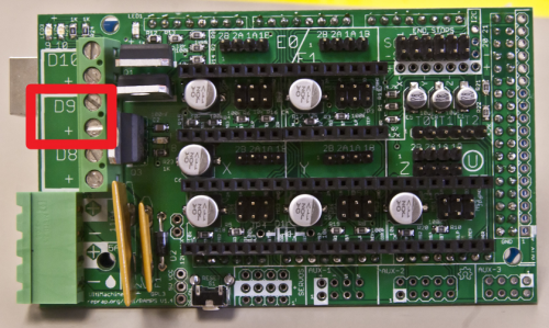
I then connected all these fans to D9.

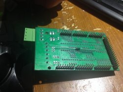
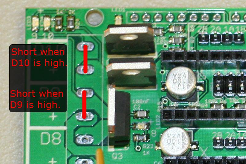
I’d like to take a sidetrail a moment. Power terminals D8, D9, D10 are simply high-power N-Channel MOSFETs controlled by PWM from the Arduino Mega’s D8, D9, and D10 pins. If you’d like the exact specs, here’s the datasheet.

Ok. Now we have a few things to set in firmware to get the fans to act correctly. First, make sure you are using the option under Configuration.h

  • #define MOTHERBOARD 33

This sets the three power channels on the Ramps to function as the following:

  1. D10 = Extruder Heater (hot-end)
  2. D9 = Fans
  3. D8 = Heated Bed

Now that is setup, then everything should work hunky-dorky, right? Well, kinda.

I was having two problems. First, the fan didn’t come on automatically, I had to send the G-Code command “M106 SXXX” to get it to turn on, the XXX being a number between 0-255 to set the PWM of the fan (also, the command M107 used to be to turn it off, but now we just send “M106 S0”).

Second problem, my fan didn’t like to kick on with PWM. Sometimes it did, sometimes it didn’t. Often, I’d start a print only to find my hot-end melting the effector plastic. Sigh.

Now, some people who know Marlin better than me will probably point out the option under the Configuration_adv.h,

  • #define FAN_KICKSTART_TIME 100

The number is the number of milliseconds to drive the fan at full speed before switching to a temperature based PWM. Now, I tried tweaking this number a bit, but I found my fan would still lock up during times it would slow. Eh. That is one reason I write this, if others have solutions, please add them in comments. :)

What I ended up doing was finding the option to have my D9 channel to run at full power all the time.

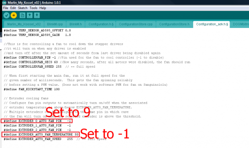
Under the Configuration_adv.h file I found the options to define the extruder fan’s behavior. First, I setup the D9 channel as our fan channel by setting

  • #define EXTRUDER_0_AUTO_FAN_PIN 9

Then, I changed the kick-on temperature to -1, meaning the hot-end would need to be below freezing for the fan to turn off. So, a hackish always on switch.

4. Physical Print Calibration

“But I bought a Kossel ‘cause it’s got an Auto-_Probe!” Ya, I’m humble enough to state those words did run through my mind. Yet, I’ve learned, the auto-probe is like many things in electronics, nice to have, but does not replace the ability or the understanding behind it. I’ll go as far as stating, the auto-probe _is meant to keep your physical calibration on track, even after heavy use, rather than compensate for poor calibration_._

Alright, to calibration.

I couldn’t find any Kossel Mini specific guides on how to calibrate the machine, but I found a lot of scattered information in the

After going through many posts I pieced together my own method for calibration. But the standard blog on the issue is:

Before we begin calibration, let’s define and agree on what we will be calibrating.

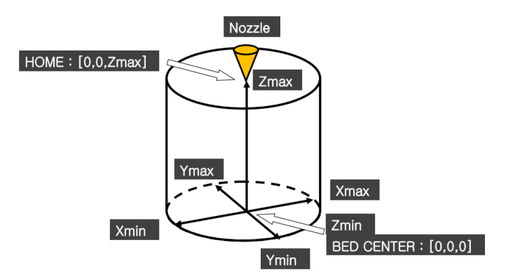
(Image shamelessly, and maybe illegally? Copied from Blokmer’s Kossel Build guide)

Ok, here we go:

Step #1 – Calibrate ZMax

This takes care. Go to Configuration.h and set,

  • #define MANUAL_Z_HOME_POS 270

This is going to tell your printer you have a build volume larger than you do, but we do this so the firmware wont stop us as we try to move the hot-end as close to the bed as possible. Now, perform the paper-test.

For the sake of brevity, I’m going to define the paper-test once, then simply refer to it as the paper-test.

The idea is eventually you want about a paper’s width space between the hot-end and the printer bed, when the printer is told to go to **Z0. **The paper-test consists of putting a piece of paper on the print bed, then lower your hot-end manually, 10mm steps at first, but as you get closer, 0.1mm steps. At the point the hot-end is putting just enough pressure to create a little drag on the paper, you stop going down. This is the paper-test.

Ok. You lower the hot-end carefully until it passes the paper-test. Then, send the G-Code for getting the Z position.

  • M114

The printer will respond with the current value for the X, Y, Z, and E (extruder). You only want the Z-value you right now. Take the Z-value and subtract it from the 270, this will be your new MANUAL_Z_HOME_POS. That is,

  • MANUAL_Z_HOME_POS = 270 - Z_Value obtained by paper-test.

If my explanation sucks, refer to Blokmer H07

Step #2 – Calibrate Physical Center

Now, there is a way to set the center of your build plate in your Marlin firmware, but it is better only to tweak it there after you have the physical part set pretty damn close to center. This is what I did.

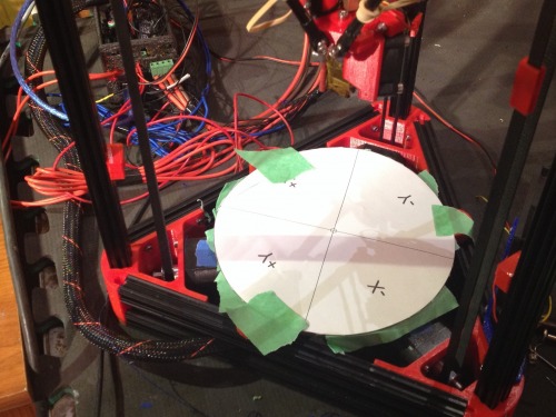
I used Eagle Cad to make a 170mm diameter circle, with exact center marked (provided below). Then, I printed it to scale on a piece of paper. I cut this paper out and centered it on my build plate, then taped it down.

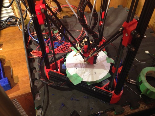
Next, I lowered my hotend until it was near to center.

Using the controls, I attempted to center the hot-end above the circle the best I could. It helps to change your angle several times before each move. Once it is center we are going to take a measurement, but something important to know before we do. The stepper motors will timeout from their held position, going into an idle position. Be careful not to let them timeout on the next two steps, since you’ll lose a little time by needing to start over. To keep them engaged, simply micro step one direction, then right back.

**

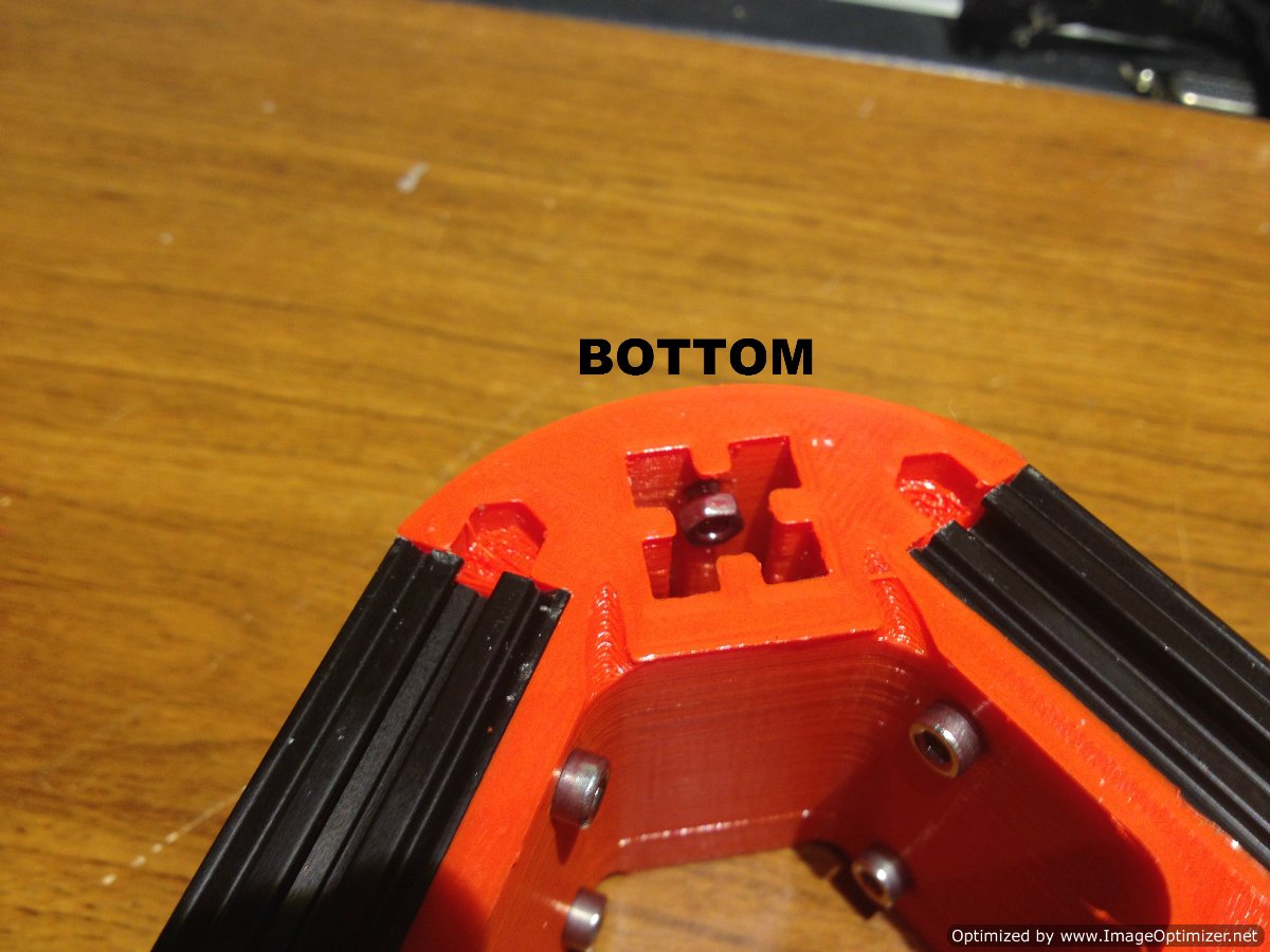
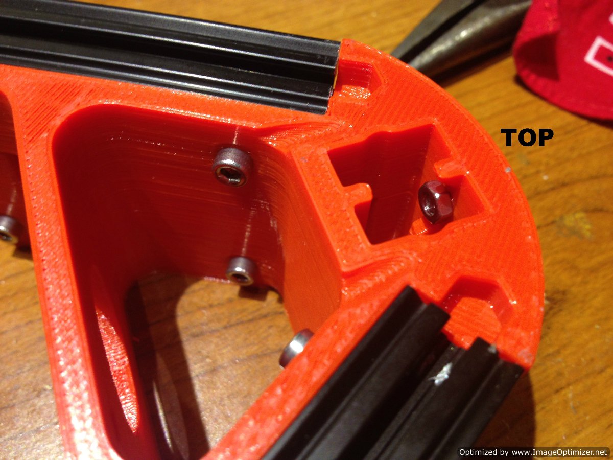
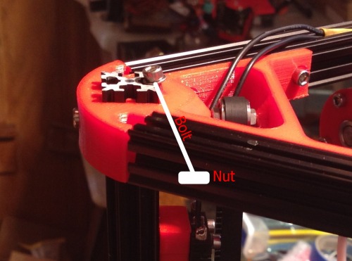
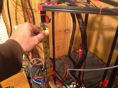
**Ok, measure from the top of one of the carriages to the bottom of the plastic on an end-stop, basically, where the end-stop button would be if it was pressed. Also, the end-stop doesn’t matter since our goal is to get them all the same.

Alright, at this part you need a saw that will give you a square cut. I used a speed-square and a circular saw. Also, smaller board, like a piece of trim board. Cut a piece of wood the same length as you measured.

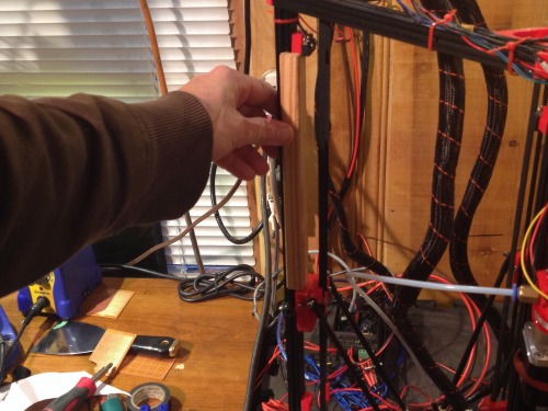
Take the piece of wood to the printer. Lower the hot-end to Z0. Then, re-center using the target-template. Now, take the cut wood and put it between each end-stop and the top of its respective carriage, being careful not to let the motors go idle. If the end-stop is too high, lower it until it is flush against the wood. If the wood will not fit, raise the end-stop until it does, making sure it is flush. In this manner you are assuring each arm is equidistant from the print bed, while maintaining the hot-end centeredness.

After this is complete, you must repeat Step 1. This sets centeredness and Z-Offset.

Now, test this by sending the G-Code:

  • G X0 Y0 Z15

If all worked, the hot-end will magically find its way to the center of the print bed, while staying 15mm above the surface. If that goes well, microstep the hot-end back down to the surface to assure we maintained the correct Z-Offset (aka, print volume).

Step #3 – Flat Print Surface

Even after all this, we still aren’t done. There is another variable to calibrate on the Kossel, the flatness of the plate.

We have already calibrated the Kossel’s print volume height. This means if we send the command G X0 Y0 Z0 then the hotend-should come to rest at the center of the print bed, about .1mm above the surface. But, delta printers have an additional variable of flatness. Consider the two following images:

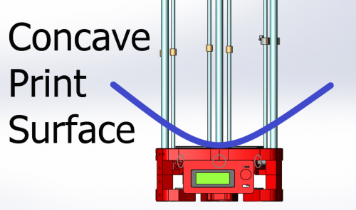
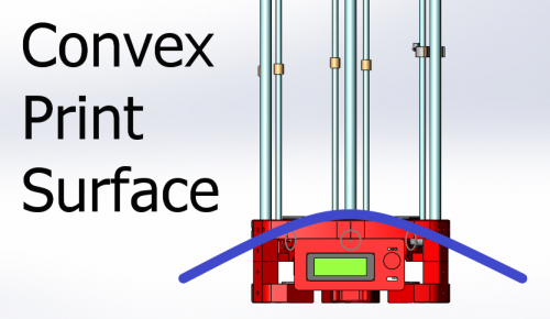
In this image the blue line is the print surface according to the Marlin firmware.

Do you see how this could create a problem? The center Z offset may be correct, but as the hot-end moves towards the edges, it gradually rises until the hot-end is resting 2-10mm away from the print surface.

Let’s look at the other, possibly more damaging, scenario.

If the print bed, according to firmware, is convex, then the hot-end might be correct when at center, but as you get to the edges, the machine tries burying your hot-end into the glass plate.

This is why Johann’s auto-probe was such a nifty addition to the Kossel build. But let’s not get ahead of ourselves, physical calibration first.

Well, that’s sort of a lie. To correct for flatness we are going to adjust the firmware. The flatness of a Kossel is reliant on the variable DELTA_RADIUS and it is the sum of several variables. So, to adjust DELTA_RADIUS we focus in on either increasing or decreasing one of the variables. I picked DELTA_SMOOTH_ROD_OFFSET at random.

Ok, the adjustment is pretty straight forward, but requres tinkering to get it right. But before we make an adjustment we need to know what direction to go. We can determine this by visually comparing difference between the distance between the hotend and the print surface when the hotend is at the center, and the distance between the hotend and the print surface when near one of the towers. Let’s go back to pictures.

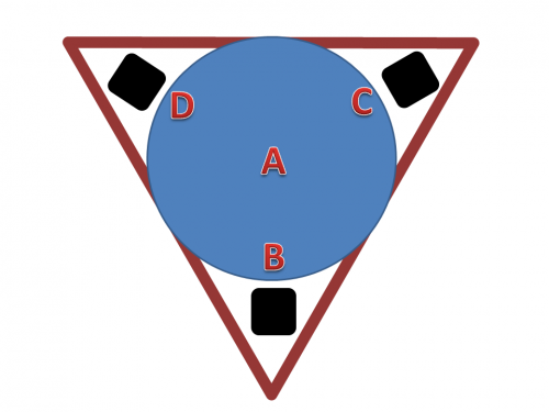
This image is to give you an idea what points we want to compare for flatness. For instance, if Kossel passes the paper-test at point A, then it should at points B, C, and D.

But if the Kossel passes the paper-test at point A, and is too high at B, C, and D then you have a concave print surface.

Likewise, if the Kossel passes the paper-test at point A, and is too low at B, C, and D then you have a convex print surface.

  • B Height > A Height = Concave
  • B Height < A Height = Convex

One more bit, you maybe asking how to find the spots B, C, and D. Well, I used the following calculations

  • Xb = (Build Radius) * COS * (Angle of B tower)
  • Yb = (Build Radius) * SIN * (Angle of B Tower)

Also, know your towers should be at angles: 90, 210, 330

If you have the same build radius as me, 170, then your points should be.

  1. Y70, X0
  2. Y-35, X-60
  3. Y-35, X60.62

But remember, we are really looking that all four points pass the paper-test.

Let’s move on to how to make the adjustment. I will not go into the math explaining how adjusting DELTA_RADIUS affects flatness, mainly because I don’t understand it. But secondly, because we don’t need to understand it to adjust it. Just know the following,

  1. Increasing DELTA_SMOOTH_ROD_OFFSET lowers the hotend.
  2. Decreasing DELTA_SMOOTH_ROD_OFFSET raises the hotend.

Really, it is changing the firmware’s idea of flatness.

Now, make the adjust from the visual information you collected by comparing point A to point B, C, and D. Then, comparing them again, adjust again. Compare, adjust. Ad infinitium.

Please, don’t think your done. Making these last adjustments means you really need to go back and start from Step #1 and work through them a second time, since any adjustment throws the previous adjustments off alittle. So, it is true, adjustment is an infinite process of error reduction and perfection will never be achieved. Be happy with pretty damn close :)

6. Auto-Probe

Physical calibration is done, now let’s examine what makes us Kossel users, our respective auto-probes.

The auto-probe is meant to keep Kossel Mini printing flat. That is, it is meant to adjust for slight inconsistencies in the print bed or minor mechanical disproportions.

Alright, as the rest of this article, I don’t plan to re-hash stuff that has already been covered. Such as setting up the auto-probe. Just refer back to Blokmer, or B3DP. But here are a few things I feel they missed:

#1 – G28 CANCELS G29 DATA

This I feel is the most important omission from the calibration guides. G28 is the G-Code to home the tower end-stops, just know whenever you do this, it will cancel the readings you took from the auto-probe. And beware, Slic3r adds a G28 command before every print.

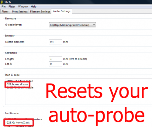
To remove this from Slic3r,

  1. Go to “Printer Settings”
  2. Under “Start G-Code” delete “G28; home all axes” line.
  3. Under “End G-Code” delete “G28 X0; home X-axis” and replace it with, “G1 X0 Y0 Z220 F5000”

Step number three is just a suggestion, but you do want your hotend to back away from the print when done, so you don’t catch anything on fire. You just don’t want to reset your auto-probe data.

And yes, I spent 20 hours or so adjusting my auto-level and scratching my head everytime my print didn’t adjust respectively. (If it wasn’t for Hoff70, I’d still be scratching my head).

I’m not smart, just obessive.

#2 Finding the X, Y, Z Offset of the Z-probe from Extruder.

The Z-probe doesn’t sit directly over the tip of the hot-end, so we have to adjust for this offset. To find this number, I did the following.

  1. Place and center the paper-template.
  2. Send the command: G X0 Y0 Z10
  3. Put the auto-probe in its active position (as if to take readings).
  4. Using Repetier or Pronterface, move the effector from the hotend being centered, until the tip of the Z-probe is centered.
  5. Then lower the effector until the Z-probe passes the paper-test.
  6. After, send G-Code: M114. The output is our auto-probe offset.

Take your readings and put them into the three defines in Marlin

  • #define X_PROBE_OFFSET_FROM_EXTRUDER
  • #define Y_PROBE_OFFSET_FROM_EXTRUDER
  • #define Z_PROBE_OFFSET_FROM_EXTRUDER

As for directionality, I found if my X or Y numbers were negative, I was telling the firmware my auto-probe was offset into the -X or -Y regions. Of course, the Z-probe offset is always negative, or you’d be in trouble.

#3 – Visualizing Auto-Probe readings

This is another important piece I feel guides leave out. What does the auto-probe data mean?

Don’t ask me, that’d take math. I’d much rather look at pictures. So, how do we turn the data into a picture? Well, there are several methods, but really, any program that will turn a set of points into a plane.

One of the guys from the Delta Google Group wrote this Python script for MATLAB.

Buuut, I don’t have MATLAB and I’m not currently tied to a university, so I had to think of another way. Well, my profession is mental health and I use Excel for a lot of statistical analysis (hey, SPSS costs money, too). Anyway, here are the steps I took to visualize the data in Excel.

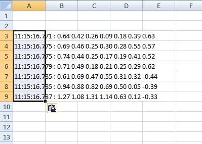
1. Run Auto-Probe. Once auto-probe is done, it’ll send back a set of points. Copy them.

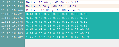
2. Paste the points into Excel. It’ll complain about formatting, press OK.

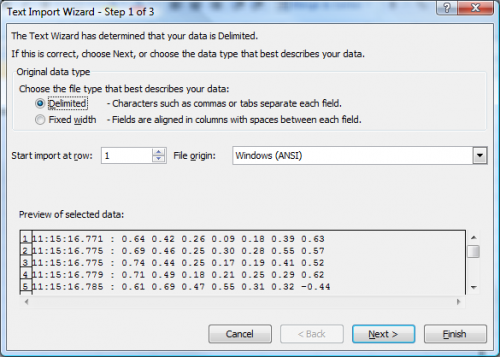
3. If you click on the formating options and select “Text Import Wizard.” You can then select a “Space Delimited” pasting option. Basically, this will cause Excel to translate th

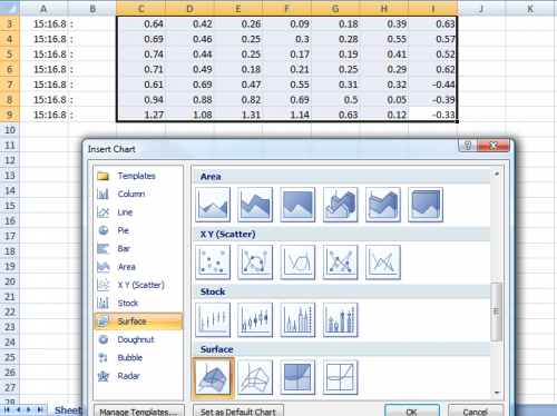
4. Once you have your data in Excel correctly, let’s make a graph. Select your data set then go to the graph type “Surface.”

5. There’s the graph.

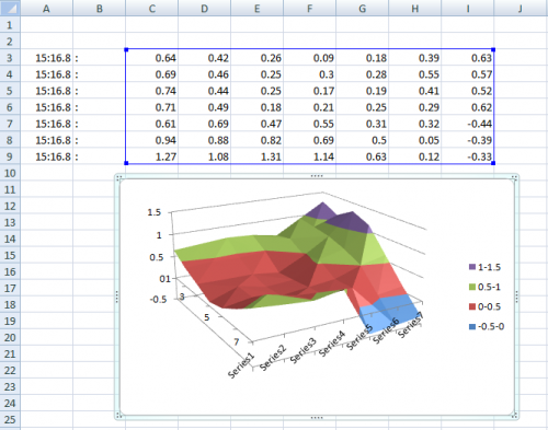
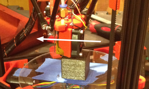
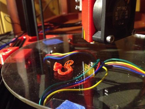
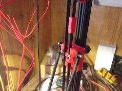
6. There are several things you can do with this data, but only if you have a point of orientation. That is, what area on the graph represent the area on the print surface. To find the auto-probe data orientation, I built a lump on my print surface near one of the towers, like this:

Be careful, if your Z-probe doesn’t retract far enough, it’ll knock your lump into the belt.

You can adjust how far your Z-probe retracts between probing in the Marlin firmware. Under Configuration.h adjust,

  • #define Z_RAISE_BETWEEN_PROBING

If all goes well, when you run your auto-probe data you’ll get a nice lump on the graphed surface. This will allow you to make intelligent decisions regarding adjustment.

  1. One last bit I’d like to point out. None of this is going to help if your auto-probe is not mechanically reliable. But how do you tell if it is? Well, until someone corrects me, I did the following.

  2. Ran the auto-probe about twenty times.
  3. After each, I took the mean of the data.
  4. Then, after I had about twenty means, I ran the standard deviation on those means.
  5. This number is a fair indicator of how reliable your auto-probe is mechanically. That is, are the readings it is giving you reliable. The smaller the number, the more reliable.

Of course, I’m not great with math and I’m pure hack, so someone with more understanding of the logic let me know if that is incorrect.

And with that I’ll close by saying: I’m a hack. I wrote this article not to point out everything I know, but rather, what I’ve learned. If anyone finds incorrect information, please comment; I’ll make changes quickly. The last thing I’d like to do is steer someone wrong.

Kossel Mini Build

Originally posted on www.letsmakerobots.com

I thought I should give my Kossel a “Robot” page, since Silas asked what the Kossel was, and I told him, “A 3D Printer,” to which my precocious son replied, “No, it’s a robot.”

A lot of the information here is a copy from my build blog, but I’ve re-thought it’s presentation slightly, since there preexist two build guides for the Kossel.

  1. Blokmer’s Kossel Mini Build Guide
  2. builda3dprinter’s Kossel Build Guide

Both are put together by organizations selling Kossel kits. Blokmer’s guide is much more detailed and slow paced. Of course, I purchased my kit from builda3dprinter (here on referred to as B3DP) and tried to use their guide as much is possible, that said, the B3DP guide has a lot missing information. I wont bitch too much, since I’ve enjoyed their kit, but it does bring me to how I’ll approach the information here.

I’m going to write this guide as a supplement to existing build guides. For example, the Kossel has an auto-level probe that is somewhat problematic to assemble. Both guides did a poor job of explaining several key parts of its assembly. Therefore, I’ll focus primarily on missing information.

Purchasing the Kossel materials:

I sourced a few parts from China and purchased the major parts from www.builda3dprinter.eu.

eBay and Fasttech

3 x NEMA 17 Motors: $42.00

1 x Planetary Stepper: $60.00

12V, 30A Power Supply: $31.39

Ramps and A4988 Drivers: $31.00

Arduino Mega: $15.81

J-head MK-V, 0.4MM Nozzle, 1.75MM: $36.99

For the rest, I bought several “kits” from www.builda3dprinter.eu.

B3DP Kits

Kossel Kit (plastic parts): $55

Nuts and Bolts kit for Kossel: $30

OpenBeam Kit for Kossel: $70

Rails to Wheels conversion kit: $50

The rest: $115

Shipping: ~$50.00

Total for Essentials: $587.19

After purchasing all the essentials I bought a few things I felt would make the build neat.

Scrunchy Wire Wrap: $10.02

Little zip-ties x 100: $3.85

Big zip-ties x 50: $4.85

Colorful heat-shrink x 140: $11.78

Total for Neatness: $30.50

Total Essetials and Neatness: $617.69

Regarding www.builda3dprinter.eu

I need to say I’ve mixed feelings towards B3DP. Being a mental-health worker, when someone has mixed feelings we create a T-Chart of pros and cons. Here’s mine on B3DP kit.

Cons:

  1. Shorted ~20 M3 Nuts.
  2. Six weeks for processing and delivery
  3. No clear documentation on the effector provided
  4. Missing Allen key, springs, and safety pin (for auto-probe). This is not included in their list of what’s not included.
  5. Pin connectors are cheap and not reliable
  6. Huge holes in documentation (Blokmer rocks this one).

Pros:

  1. Plastic part quality is excellent.
  2. Responded to delays by giving me a free borisillicate plate.
  3. Communicate well (they responded quickly to all my questions).
  4. Their kits **do **work well together.

In fairness, I’m not done with the build, but writing this out, I’d say I would buy B3DP kits again.

The bit it’s difficult to put a price on is part precision and synergize. Since the parts are meant to work together, calibration is much simplier (still not easy). For instance, instead of having to measure out the length of rods, carriage offset, etc. B3DP provided a Marlin (firmware for delta) with these measurements already input. In sum, half of the calibration is already done by B3DP.

Purchase “Doh”s!

1. Effector mismatch:

B3DP provided me with a MK V end effector and I bought MK IV J-Head extruder that was advertised as an MK V. Point to you eBay. So far, this hasn’t caused any problems, I simply pulled the brass end off my extruder and pushed it into place. Not sure of the open area between the effector plastic and the PTFE tubing will cause me problems down the road, like filament bunching.

2. Must have a Geared Stepper motor for extruder:

I purchased my stepper motors in a lot of five. I thought, “I’ll use 3 for the X, Y, Z axes and one 1 for the extruder.” Well, this is where I should have done more research. The original design for the Kossel requires a NEMA 17 Geared Stepper Motor. So, I broke down and ordered a geared stepper-motor for the extruder. I was a little under budget and felt it was a better choice rather than struggling trying to get the current motor I had to work with what B3DP sent.

But to be clear the extruder from B3DP is built for a stepper-motor with a 8mm shaft. Actually, the parts are from the original design which called for a geared-stepper motor and a spur-gear with 22 teeth, with a 8mm diameter shaft. The “common” NEMA17 has a 5mm diameter shaft. I’ve seen a few extruder designs that use a regular stepper and a 5mm diamter spur-gear, but that is not what comes with the B3DP kit.

Assembly

Like I stated, I’m no going into a lot of detail about the assembly, since there exist two guides. But I’ll include time-lapse of most of the build (what was easy to film) and notes on stuff not in the exist build-guides.

1. Jig Setup & Traxxas Ends

Assembly Video

The Blokemer guide states I should tap and drill the Traxxas ends and the carbon rods. I bought a metric tap and die set from Harbor Freight, but when I examined the pieces I received from B3DP I noticed the headless bolts were too small to catch the inside of the carbon rods. Also, I wasn’t sure how to use my tap and die; this devolved into the realization I had the wrong thread sizes. Makes sense, I was using a US tool and parts from everywhere else but the US.

Well, I lucked out. According to the B3DP manual you don’t need to tap anything. Just screw the headless bolts into the Traxxas ends, then use slow-setting Epoxy to glue the ends into the carbon rods. Screwing the headless bolts in the Traxxas ends went great. Um, gluing was another matter.

Not much to say about setting up the jigs for the carbon rods and Traxxas ends. Just follow the instructions on pages 3-6 of the Blomker guide. I used a square and a speed-square, the square to align the rails flush, then the speed-square to align the machine screws at one end. I’ve read that the arms can deviate from the 180mm outlined by the guide, but they should all be the same length. My goal was to identify rods longer than the others and file them down a little.

Post-build note: I found to “spare” objects in my plastic parts that came from B3DP–I realized they are jig bits. Doh.

2. Gluing Traxxas Ends (and a big F’up)

Video

I bought some cheap slow setting epoxy from Harbor Freight. I mixed it with a chop-stick (a favorite tool) and began to apply it to the Traxxas ends. Then, I f’ed up.

I dropped one of the Traxxas ends into the epoxy. I tried cleaning it in alcohol and acetone. But there was still some residue that prevented the ball-joint from moving as freely as I wanted. Sigh. I went ahead and ordered more Traxxas heads, so, if anyone needs an extra because they dropped it in epoxy, just let me know. I’ll have eleven.

One more note, be sure to wipe excess epoxy from the Traxxas end and rod joint. I was worried about an improper seal between the two and left the globulated extra. It leaked into the crevices of the 1515 Beam. Of course, I thought, “I’ll just make sure to turn the yucky part inside when I put the pieces together so it’s not noticeable.” Well, the nuts bolting it to the plastic pieces are also on the inside. In short, it caused a lot of problems. I’d wipe them off before setting them in place on the jigs if I could do it over.

3. Bottom Triforce Assembly

Video

I didn’t like the name “Bottom Assembly” so, I renamed this step: Bottom Triforce assembly. For the most part, smooth sailing. Just make sure you barely screw the nuts on. If they are too tight you can’t get the plastic lips to close around them. Also, they have a top and bottom.

Adding the shafts to the bottom Triforce was a little tricky. First, it should be noted, there is an “up” and a “down” to the Triforce pieces:

]

The little circular tabs on the bottom Triforce assembly are for printing purposes and may be removed with a sharp knife and steady hand. In the absence of a steady hand, a lot of blood and an emergency-room visit will suffice.

Also, don’t screw any bolts down too tight until you press all pieces together. I had reviewed the section in the Blokmer guide, pages 28-32, but I realized the need for give from all sides was greater than expected. You’ll notice towards the end of my video I was struggling not to look like a complete idiot trying to push all the pieces together.

Of course, I didn’t realize this until I already had bolted the bottom Triforce down and started trying to shove the first shaft in place. I quickly pulled the bottom apart, flipped the odd piece I had so all my plastic pieces had the two-prong guide at the “top.”

Now, I’ve seen half-dozen different ways to press the 1515 into printed plastic. I tried my heat gun, but was really wary I’d deform a piece and I would have to wait 6 weeks to get another from B3DP. I ended up using the following tools:

To press the rods in, I started the rod into the first nut. Then, when it started to get tight, I put a little bike oil (the green bottle) around the edges, flipped over the assembly, and put it in my lap. I pressed the end of the rod I had started against the tile floor and beat on the receiving end (assembly) with a balled fist.

Well, this worked great. A little too great. The rod slipped past being flush. This is where the screwdriver and hammer came in. I simply left the assembly in my lap, but raised the rod off the floor. Then with the tip of the screwdriver against the end of the 1515 rod, I tapped against the screwdriver with the hammer. This allowed me to align the 1515 rod flush with the bottom plastic of the Triforce assembly.

4. Carriage Assembly

Video

Carriages assembly went pretty well. I had to tap the holes for most of the bolts on the carriages, since there was printer-webs still in the holes. But after the holes were clear it was pretty straight forward. I followed the guide from B3DP.

A few notes: If you haven’t sorted your bolts, might be a good idea to do it now. If all your bolts are lumped together digital-calipers are a godsend. You just measure from directly under the head, to the end of the shaft.

There are three nuts that will need to be pressed into the plastic of the carriage assembly. I used a heat gut to soften the plastic of the intended holes, then pressed the nut slightly in place by placing the tip of a flat-head screwdriver over the nut and tapping it with a hammer. This method worked well. One exception, there are three nuts, but two of the bolts are 25mm and one is 16mm. The 16mm bolt is not long enough to catch the threads of the nut unless you tap it deep into its hole. I hope this picture makes it clear:

5. Motors and Endstops

Bottom endstops and motors went smooth.

Only bits of advice on the motors are: Make sure you tap the holes in the plastic to prevent any plastic shards from misaligning your bolt as you try to screw it into the motor hole.

Also, don’t tighten any bolts down until all your bolts are started correctly. I found they often were misthreading, which I attributed to such a harsh angle.

Oh, one more bit, purchase a long 2mm Balled Allen Key for this process. As you may notice at the beginning of my video I tried with a short, balless Allen key to no avail.

6. Carriage Arms and Effector Assembly

Video

A couple notes,

The carriage assembly is pretty straight forward, just make sure you follow the instructions and don’t get in a hurry. But the effector I had a little difficulty putting together. Mainly, the round part of the J-head wouldn’t fit into the hole. I’ve tried to avoid using a heatgun as much as possible, but here I used it to warm the plastic enough and pressed the J-head into place.

  1. Top Triforce, PSU, Ramps 1.4, and Attaching Effector

Video

Here I become a little peeved at B3DP. First, there are three parts they do not include in “The Rest” kit, but also don’t mention in the “What’s not included” section. They are the spring, safety pin, and Allen-key for the auto-level.

The auto-level bit is a little tricky to put together. You will need to source three parts: The safety pin, Allen-key, and springs. I ordered an Allen-key off eBay. The safety pin I “borrowed” from my wife’s things. And the springs I pulled from some old pins. After much fiddling I was able to piece something together.

Now, I need to state, in my original blog I was a little unfair to B3DP. I bitched about them sending a button-switch for the auto-probe. The problem was they provided a button switch instead of an button and arm switch.

Arm and Button

Button Switch

This should not have bothered me too much, since the three end-stops worked. But when it came to the auto-level, the Allen-key crook was supposed to catch the metal arm of the above shown switches, guiding it down to the button. Well, I found when the Allen-key came to sit on the button, instead of pressing it down it would slide either to the left or right. And it didn’t seem to matter how much tweaking I did, I couldn’t get it to sit right. In the end, I bought the “appropriate” switch at Radio Shack for $3.

Here is what my auto-level looked like after tweaking. When I tested it unmounted it worked.

But, when I mounted the auto-probe and started using it, I found the arm would catch underneath the safety-pin bolt. Hmm.

Therefore, I feel I owe B3DP half an apology.

I ended up using the switch I was sent, effectively, and I apologize for bitching about the wrong switch. But, to get the switch I was sent to work properly, I had to layer heatshrink, over, and over. This builds the arm up to the point it can’t help but catch the button. And the heatshrink has some natural resistance to it. This necessary modification probably needs to make it into the B3DP guide.

Regarding the power-supply.

I tried buying a cheap computer-power cord from eBay. But after I sliced the end off and found less copper than in telephone wire. I sacrificed one of my old computer power cords. The powercord wasn’t as long as I’d like, but it had enough copper to pull the possible 30A the PSU could source.

To wire the PSU,

  • Green <—> Ground
  • White <—> N(eutral)
  • Black <—> L(ive)

Also, if you are using that fasttech.com PSU, I noticed it came to me with the 240v as default. If you’re in the states make sure you flip the switch on the side.

After wiring my PSU to the Ramps I turned it on and looked for blue-smoke. Nothing. Waahoo!

But I had another problem. The Mega underneath wasn’t getting power. Well, I scratched my head for a bit and then actually read the Ramps manual. Apparently the diode that had been taped to the underbelly of my Ramps is what enabled it to be powered from a 12V PSU. I soldered it in place.

After soldering the diode everything appeared to be working. I continued to wire everything else up like proper.

12V to Arduino Mega Diode placement

Here, I switched gears and put the top Triforce together.

One note I’ll make. Again, the top Triforce has a “bottom” and a “top.” It has to do with the tensioner bolt, it must angle from the top-outside to the bottom-inside. Like this,

After, I got a hankering to actually put the top on and the belts in place. It took a little courage, since B3DP sent my timing belts in one role. I had to make cuts and was worried they had given me just enough belt and if I made a cut that was a little off would have to wait on another belt. But it was in vain, I had enough.

To cut the belts I just strung them up as shown and left about four rubber-teeth past the end of the linker groove. The little extra room can be adjusted when the top Triforce is put on. There are three tension bolts for this purpose.

This is what the belt should look like in place, except the should go below the carriage or it will knock into the end-stops before carriage.

(Sidenote, from here on I’m using a lot of pictures, since the Kossel is a little difficult to video given its physical size)

I then tightened the top Triforce and quickly hooked up the Ramps. I uploaded the Marlin firmware and was able to get the motors to respond to one direction. The problem came when I tried to hook the cooling fan to the Ramps. Two of the three FETs were putting out 0Vs. Waaa-waaah.

Apparently, the power control FETs on the Ramps were bad?

I found out later (Brassfly and Bdk6 actually figured it out) that it was not bad FETs. It was a trace-short somewhere on the first 12V power rail. Oh well. I ordered another Ramps board for $14 and took a break from the build for 18 days while it found its way to me.

8. It’s Alive!

Video

The evening I received the new Ramps board I wired everything up. Sure enough, I powered the thing on and all the blue-fairies stayined in their Silicon homes. I then ran the Blink sketch to check the power FETs on pins 8, 9, 10. They all powered on like expected, spitting out 12Vs.

Next, I uploaded Blokmer’s Marlin sketch. Big mistake.

Blokmer and B3DP both provide a Marlin sketch with “typical” measurements already plugged into the Configuration.cpp. I didn’t know this. I had essentially put diesel into a gasoline engine.

  1. Blokmer’s Marlin Firmware Specific to Blokmer’s Kossel, Pronterface, and Slicer (.zip; for Windows)
  2. B3DP’s Setup Page. It links to Marlin Firmware specific to B3DP Kossel, Pronterface, and KISSlice.

Of course, I pulled a lot of my hair out using Blokmer’s firmware with a B3DP build. In the end, I downloaded B3DP’s Marlin and Blokmer’s zip file. That is, I used the appropriate Marlin with Pronterface and Slicer.

Before I move on though, I’d like to go over wiring.

Here is the B3DP wiring chart:

Of course, my stepper-motors had different color wires, but I guessed and got it right. Really, I figure they would either move up or down, then I could switch them if needed. A word of caution, make sure you wire each stepper to its corresponding end-stop. If not, when you home the end-stops for the first time one or two of the motors will stop, but the other two or one will continue because their end stop hasn’t been triggered, resulting in your belt(s) coming loose. E.g., motor X will hit end-stop Z, but not turn off because the X end-stop hasn’t been switched. And the X end-stop wont switch off because motor Z has stopped because its end-stop has be triggered.

Clear as mud? Just make sure each end-stop is wired to the appropriate motor.

Regarding the thermistor, it is non-polarized. Just plug it in.

Ok. I’m going to consider the “Mechanical” section of this build complete. Now, I’ll begin working on the hard stuff: Calibration.

Metallurgy 101 - AVR UART

This is a continuation of my Robot Metallurgy 101 – AVR Lesson Journal

I started looking through Newbie Hack’s tutorials on AVR trying to work up the energy to tackle First LCD Program. Many don’t know this, but I despise workings with LCDs. I think it is two parts, one, I live in a world with high-resolution screens embedded in everything from coffee-machines to toilets. Trying to settle with an old school LCD doesn’t cut it for me. Furthermore, wiring a non-serial interface LCD is a ever loving pain.

But looking at the rest of the Newbie Hack tutorials I knew I would need some way to display information from the ATtiny1634. I thought about it and compromised: I’d focus on UART next. That way I could display information on my desktop screen.

I began reading about UART on AVR; here are some of the good ones I found,

  1. Newbie Hack’s One Way Communication
  2. Newbie Hack’s Two way Communication
  3. maxEmbedded’s USART

After reading the articles I opened up the ATtiny1634 datasheet and decided I would start by trying to output “ALABTU” to a serial-port into Real Term.

It took me maybe an hour or two to get something working; here is what I learned along the way.

1. AVR UART is Easy.

The following code sets the baud rate on the ATtiny 1634 using the UBBR chart from the datasheet, then, transmits the letter “A.”

UART Code v01

//
// UART Example on the ATtiny1634 using UART0.
// C. Thomas Brittain
// letsmakerobots.com

#define F_CPU 8000000    // AVR clock frequency in Hz, used by util/delay.h
#include <avr/io.h>
#include <util/delay.h>
// define some macros
#define UBBR 51 // 9600, .02%

// function to initialize UART
void uart_init (void)
{
	/* Set baud rate */
	UBRR0H = (unsigned char)(UBBR>>8);
	UBRR0L = (unsigned char)UBBR;
	/* Enable receiver and transmitter */
	UCSR0B = (1<<RXEN0)|(1<<TXEN0);
	/* Set frame format: 8data, 1stop bit */
	UCSR0C = (1<<USBS0)|(1<<UCSZ00)|(1<<UCSZ01);   // 8bit data format
}

void USART_Transmit( unsigned char data )
{
	/* Wait for empty transmit buffer */
	while ( !( UCSR0A & (1<<UDRE0)) );

	/* Put data into buffer, sends the data */
	UDR0 = data;
}

int main()
{
	uart_init();

	while(1){

		USART_Transmit(0x41);
	}
}

  • Line 10: This creates a macro for the UART Baud Rate Register (UBBR). This number can be calculated using the formula on page 148 of the datasheet. It should be: UBBR = ((CPU_SPEED)/16DESIRED_BAUD)-1. For me, I wanted to set my rate to 9600, therefore: UBBR = (8,000,000/169600)-1; Or: UBBR = (8,000,000/153,600)-1 = **51.083. **It can have a slight margin of error, and since we can’t use a float, I rounded to 51.

  • We then setup of function to initialize the UART connection. Lines 16-17 load our calculated baud rate into a register that will actually set the speed we decided upon. This is done by using four bits from the UBBR0L and UBBR0H registers. If the » is unfamiliar to you, it is the right-shift operator and works much like the left-shift, but yanno, in the other direction.

  • Still in initialization, line 19 enables both the RX0 and the TX0 pins (PA7 and PB0 respectively). I’m not using the TX0 pin yet, but I figured I might as well enable it since I’ll use it later.

  • Line 21 sets the bits to tell the Tiny1634 what sort of communication we want. We want 8 bit, non-parity, 1 stop bit. Enabling USBS0, UCSZ00 and UCSZ01 give us these values.

.

  • Line 24 is the beginning of the function that’ll transmit our data. Line 27 checks to see if the ATtiny1634 is finished transmitting before giving it more to transmit. The UDRE0 is a bit on the UCSR0A register that is only clear when the transmit buffer is clear. So, the while ( !(UCSR0A & (1«UDRE0)); checks the bit, if it is not clear, it checks it again, and again, until it is. This is a fancy pause, which is dependent on the transmit buffer being clear. Line 30 is where the magic happens. The UDR0 is the transmit register, whatever is placed in the register gets shot out the TX line. Here, we are passing the data that was given to the USART_Transmit function when it is called.

  • Line 39 is passing the hex value for the character “A” to the transmit function.

This was a bit easier than expected.

Here was the output from Code v01.

After a little more tweaking and watching Newbie Hack’s video on sending strings to an LCD, I adapted NH’s code to be used by my UART_Transmit() function I ended with a full string of “ALABTU!” on the serial monitor.

I did this by creating a function called Serial_Print, which is passed a character array (string). StringOfCharacters is a pointer and will be passing each character to the UART transmission. Pointers are simply variables that point to the contents of other variables. They are highly useful when you are looking at the information contained in a variable rather than changing variables’ data. Newbie Hack did an excellent job explaining pointers.

Now, whenever the Serial_Print function is called it starts the loop contained. The loop (line 60, code v02) continues to point out each value contained in the string until it comes across a “0” at which point it exits the loop, and subsequently, the function call.

UART Code v02

The above code provided the following output in the serial monitor. (ALABTU!)

At this point my simple mind was quite pleased with its trite accomplishments and I saw building a library out of my code being pretty easy. But a few problems I had to solve first:

A. Dynamic baud rate initialization.

In Arduino C Serial.begin(9600) initializes the serial connection and sets the baud rate. This is dynamic regardless of running an Arduino Uno at 1mhz or Arduino Mega at 16mhz. I wanted the same functionality; being able to set the baud rate by passing it to the intialization function, uart_init().

I solved this by adding the formula in the uart_init() function (see lines 21 and 38 of code v03). In short, the F_CPU macro contains whatever speed the microcontroller is set, in my case 8mhz, and the user knows what baud rate he wants the code set, so I had all the pieces for to solve the UBBR equation. I made F_CPU part of the calculation and allowed the uart_init() to pass the desired baud rate to the formula. This allowed me to set the baud rate simply by passing the uart_init() function whatever baud rate I wanted. e.g., uart_init(9600);

B. Carriage-return and line-feed at end-of-transmission (EOT).

In Arduino C every time you send serial data, Serial.print(“What’s up mother blinkers!?”), there are two characters added. If you are as new to the world of microcontrollers as me, you may have had headaches finding where these extra characters came from whenever you printed something serially. Arduino C’s Serial.Print() function automatically adds the carriage-return and line-feed characters. In ASCII that’s, “13” and “10” and in hex, “0x0A” and “0x0D” respectively. Arduino C does this, I believe, as a protocol flagging the end of a transmission. This is helpful for the serial receiver to parse the data.

To solve this I simply created two functions CR() and LF() that would transmit the hex code for the line-feed character and the carriage-return. I went this route because not every serial devices excepts them, for instance, the HM-10 that I’m in a love-hate with excepts no characters following the AT commands you send it. I wanted an easy way to send these characters, but not so embedded I had to pull my hair out trying not to send them.

The following code is what I ended with,

UART Code v03

The above code provided the following output. Notice my serial monitor automatically recognized the CR and LF character, which is why “ALABTU!” is one per line, and always left-justified. Booyah!

Ok. I’m not done yet, here is what I’ll be working on in the evening over the next few days,

Receiving data is a little more complex…a little.

2. RX is less easy

I started by reviewing Newbie Hack’s code One Way Communication from Chip-to-Chip, more specifically, his code about the receiving chip. I skipped the part about intilization, since I’d already done that and went straight to his receiving code,

include <avr/io.h>
int main(void)
{
	DDRB |= (1 << PINB0);

	//Communication UART specifications (Parity, stop bits, data bit length)
	int UBRR_Value = 25; //This is for 2400 baud
	UBRR0H = (unsigned char) (UBRR_Value >> 8);
	UBRR0L = (unsigned char) UBRR_Value;
	UCSR0B = (1 << RXEN0) | (1 << TXEN0);
	UCSR0C = (1 << USBS0) | (3 << UCSZ00);

	unsigned char receiveData;
	while (1)
	{
		while (! (UCSR0A & (1 << RXC0)) );

		receiveData = UDR0;

		if (receiveData == 0b11110000) PORTB ^= (1 << PINB0);
	}
}

This code receives data and turns on/off a LED if anything was received. It doesn’t concern itself with the values received, just whether something was received.

I was able to replicate this code and get the LED to switch states, but I quickly noticed a problem. The While loop on line 16 is stuck in checking to see if anything has been received, continuously. The problem is apparent; this freezes the microcontroller from doing anything else. Damnit.

Alright, need a different solution; sadly, the solution was something I’d been avoiding for a year, the use of interrupts.

I’m not the sharpest when it comes to electronics, before July 2012 all I’d ever done with electronics was turned’em on and checked Facebook. (By the way, up yours Facebook.) Since my hardware education began I’ve avoided learning about interrupts because they’ve intimidated me.

I won’t go into interrupts here, since I’m just learning about them. But I’ll mention there are two types, internal and external.

Internal interrupts are generated by the internal hardware of a microcontroller and are called software interrupts, because they are genereated by the CPU as a result of how it is coded. External interrupts are voltages delivered to a pin on the microcontroller. Also, interrupts essentially cause the CPU to put a bookmark in the code it was reading, run over and take care of whatever, then when finished, come back to the bookmarked code and continues reading.

That stated, I’d refer you to Newbie Hack’s tutorials on AVR interrupts. It’s excellent. Also, Abcminiuser over at AVR Freaks provided an excellent tutorial on AVR interrupts.

Ok. Back to my problem.

So, I dug in the ATtiny1634 datasheet (pg 168) and found the ATtiny1634 has an interrupt that will fire whenever the RX data buffer is full. To activate this interrupt we have to do two things, enable global interrupts and set the RXCIE0 bit on the UCSR0B register. This seemed pretty straight forward, but I found a AVR Freaks tutorial that helped explain it anyway.

Caveat, I’m learning to re-read which register a bit is found. Occasionally, I’m finding myself frustrated a piece of code is not working, only to realize I’m initializing a bit on an incorrect port. For example, UCSR0D |= (1<<RXCIE0) will compile fine, but it would actually be enabling the bit RXSEI, which is the bit you set to enable an interrupt at the start of a serial data receive. This happens because the names of registers and bits are part of the AVR Core library, but they are simply macros for numbers. In the case of RXCIE0, it actually represents 7, so coding UCSR0D |= (1<<RXCIE0) is simply setting the 7th bit on the wrong register. Not that I did that or something.

Alright, I now have the interrupt setup for when the ATtiny1634 is done receiving a byte.

UART Code v04

Of course, I didn’t add a character to character array conversion, yet. I’m not sure if I want to add this to current function. I personally would rather handle my received characters on a project specific basis. But it should really be as simple as adding character array, then a function to add each character received to the array until it is full. Then, decide what to do when the character array is full.

But Code v04 gave me the following output:

Each time the letter “A” is sent from the serial terminal a RX interrupt event occurs. The interrupt transfers the byte to a variable that is then sent right back out by the Serial_Print() function. Thus, echoing the data you send it.

3. Fully Interrupted

Ok, so, interrupts are a little tricky. Well, one trick. When you are using an interrupt that modifies a variable anywhere else your main that modifies the same variable, you’ll need to disable the interrupt before the modification. It prevents corrupt or incomplete data.

Also, I am using a poor man’s buffer. It’s a simple buffer that overwrites itself and requires an end-of-transmission character, in my case, a “.” from the transmitter to know where to cap the buffer. Still, I believe this will work for a lot of what I’d like to use it.

I do foresee a problem when I enable the second UART on the Tiny1634, since really, only one RX interrupt can run the show. We’ll see. I’m a little tired to detail things here, but here is the code I ended with and I tried to comment the hell out of it.

UART Code v05

One of the other things I did was enable the sleep mode on the Tiny1634. It is setup on line 39 and part of the main loop. It wakes on receiving serial data. I’ve not tested the power consumption, but this is supposed to make the chip drop down to ~5uA.

Nifty right? :)

Ok, code for the second UART.

UART Code v06

I was surprised. The interrupts didn’t seem to trip each other up. Of course, I only did a simple test of sending data from one terminal into the ATtiny1634 and having it come out on the other terminal. This would be: Data–>RX0—>TX1 and Data–>RX1–>TX0

So, there really shouldn’t be any reason the code would trip out, since the RX0 and RX1 interrupts aren’t firing at the same time. I’ll create a library from this code, and as I start using the library in applications I’ll do more debugging and improvement. Also, if anyone is bored and wants to critique the code, I’ve got my big boy pants on, I’d appreciate the criticism.

4. All Together!

It only took me 30 minutes or so to convert the UART code to a library. Here it is, a UART library consisting of 12 functions.

  1. USART_init0()
  2. USART_init1()
  3. USART_Transmit0()
  4. USART_Transmit1()
  5. Serial_Print0()
  6. Serial_Print1()
  7. ClearBuffer0();
  8. ClearBuffer1();
  9. LF0()
  10. LF1()
  11. CR0()
  12. CR1()

Functions numbered 0 relate to serial lines 0, which are pins PA7 (Rx0) and PB0 (Tx0). The functions numbered 1 are serial lines 1, which are pins PB1 (Rx1) and PB2 (Tx1).

USART_init

  • Initializes a serial lines. Enables TX and RX pins, assigns the baud rate, and enables RX interrupt on receive. It also sets the communication as 8 bit, 1 stop-bit, and non-parity.

USART_Transmit

  • Will transmit a single character.

Serial_Print

  • Prints a string.

ClearBuffer

  • Empties the receiving buffer.

LF and CR

  • Transmit a line-feed or carriage-return character.

This is the library code: 1634_UART.h

#ifndef	UART_1634
#define UART_1634

#include <avr/interrupt.h>  //Add the interrupt library; int. used for RX.

//Buffers for UART0 and UART1
//USART0
char ReceivedData0[32];	//Character array for Rx data.
int ReceivedDataIndex0;	//Character array index.
int rxFlag0;			//Boolean flag to show character has be retrieved from RX.

//USART1
char ReceivedData1[32];	//Character array for Rx data.
int ReceivedDataIndex1;	//Character array index.
int rxFlag1;			//Boolean flag to show character has be retrieved from RX.

//Preprocessing of functions.  This allows us to initialize functions
//without having to put them before the main.
void USART_init0(int BUADRATE);
void USART_Transmit0( unsigned char data);
void Serial_Print0(char *StringOfCharacters);
void clearBuffer0();

void USART_init1(int BUADRATE);
void USART_Transmit1( unsigned char data);
void Serial_Print1(char *StringOfCharacters);
void clearBuffer1();

//EOT characters.
void LF0();
void CR0();

//EOT characters.
void LF1();
void CR1();

// function to initialize UART0
void USART_init0(int Desired_Baudrate)
{
	//Only set baud rate once.  If baud is changed serial data is corrupted.
	#ifndef UBBR
	//Set the baud rate dynamically, based on current microcontroller
	//speed and the desired baud rate given by the user.
	#define UBBR ((F_CPU)/(Desired_Baudrate*16UL)-1)
	#endif

	//Set baud rate.
	UBRR1H = (unsigned char)(UBBR>>8);
	UBRR1L = (unsigned char)UBBR;

	//Enables the RX interrupt.
	//NOTE: The RX data buffer must be clear or this will continue
	//to generate interrupts. Pg 157.
	UCSR1B |= (1<<RXCIE1);

	//Enable receiver and transmitter
	UCSR1B |= (1<<RXEN1)|(1<<TXEN1);

	//Set frame format: 8data, 1 stop bit
	UCSR1C |= (1<<UCSZ00)|(1<<UCSZ01);   // 8bit data format

	//Enables global interrupts.
	sei();
}

// Function to initialize UART1
void USART_init1(int Desired_Baudrate)
{
	//Only set baud rate once.  If baud is changed serial data is corrupted.
	#ifndef UBBR
		//Set the baud rate dynamically, based on current microcontroller
		//speed and the desired baud rate given by the user.
		#define UBBR ((F_CPU)/(Desired_Baudrate*16UL)-1)
	#endif

	//Set baud rate.
	UBRR0H = (unsigned char)(UBBR>>8);
	UBRR0L = (unsigned char)UBBR;

	//Enables the RX interrupt.
	//NOTE: The RX data buffer must be clear or this will continue
	//to generate interrupts. Pg 157.
	UCSR0B |= (1<<RXCIE0);

	//Enable receiver and transmitter
	UCSR0B |= (1<<RXEN0)|(1<<TXEN0);

	//Set frame format: 8data, 1 stop bit
	UCSR0C |= (1<<UCSZ00)|(1<<UCSZ01);   // 8bit data format

	//Enables global interrupts.
	sei();
}

//USART0
void USART_Transmit0( unsigned char data )
{
	//We have to disable RX interrupts.  If we have
	//an interrupt firing at the same time we are
	//trying to transmit we'll lose some data.
	UCSR0B ^= ((1<<RXEN0)|(1<<RXCIE0));

	//Wait for empty transmit buffer
	while ( !( UCSR0A & (1<<UDRE0)) );

	//Put data into buffer, sends the data
	UDR0 = data;

	//Re-enable RX interrupts.
	UCSR0B ^= ((1<<RXEN0)|(1<<RXCIE0));

}

//USART1
void USART_Transmit1( unsigned char data )
{

	//We have to disable RX interrupts.  If we have
	//an interrupt firing at the same time we are
	//trying to transmit we'll lose some data.
	UCSR1B ^= ((1<<RXEN1)|(1<<RXCIE1));

	//Wait for empty transmit buffer
	while ( !( UCSR1A & (1<<UDRE1)) );

	//Put data into buffer, sends the data
	UDR1 = data;

	//Re-enable RX interrupts.
	UCSR1B ^= ((1<<RXEN1)|(1<<RXCIE1));

}

//This functions uses a character pointer (the "*" before the StringOfCharacters
//makes this a pointer) to retrieve a letter from a temporary character array (string)
//we made by passing the function "ALABTU!"

//USART0
void Serial_Print0(char *StringOfCharacters){
	UCSR0B ^= ((1<<RXEN0)|(1<<RXCIE0));

	//Let's do this until we see a zero instead of a letter.
	while(*StringOfCharacters > 0){

		//This function actually sends each character, one by one.
		//After a character is sent, we increment the pointer (++).
		USART_Transmit0(*StringOfCharacters++);
	}
	//Re-enable RX interrupts.
	UCSR0B ^= ((1<<RXEN0)|(1<<RXCIE0));
}

//USART1
void Serial_Print1(char *StringOfCharacters){
	UCSR1B ^= ((1<<RXEN1)|(1<<RXCIE1));

	//Let's do this until we see a zero instead of a letter.
	while(*StringOfCharacters > 0){

		//This function actually sends each character, one by one.
		//After a character is sent, we increment the pointer (++).
		USART_Transmit1(*StringOfCharacters++);
	}
	//Re-enable RX interrupts.
	UCSR1B ^= ((1<<RXEN1)|(1<<RXCIE1));
}

//USART0
void clearBuffer0(){
	//Ugh.  A very inefficient way to clear the buffer. :P
	ReceivedDataIndex0=0;
	for (unsigned int i = 0; i < 64;)
	{
		//We set the buffer to NULL, not 0.
		ReceivedData0[i] = 0x00;
		i++;
	}
}

//USART1
void clearBuffer1(){
	//Ugh.  A very inefficient way to clear the buffer. :P
	ReceivedDataIndex1=0;
	for (unsigned int i = 0; i < 64;)
	{
		//We set the buffer to NULL, not 0.
		ReceivedData1[i] = 0x00;
		i++;
	}
}

void LF0(){USART_Transmit0(0x0A);}  //Function for sending line-feed character.
void CR0(){USART_Transmit0(0x0D);}  //Function for sending carriage-return character.

void LF1(){USART_Transmit1(0x0A);}  //Function for sending line-feed character.
void CR1(){USART_Transmit1(0x0D);}  //Function for sending carriage-return character.

ISR(USART0_RX_vect){
	//RX0 interrupt

	//Show we have received a character.
	rxFlag0 = 1;

	//Load the character into the poor man's buffer.
	//The buffer works based on a end-of-transmission character (EOTC)
	//sent a the end of a string.  The buffer stops at 63 instead of 64
	//to always give room for this EOTC.  In our case, "."
	if (ReceivedDataIndex0 < 63){
		//Actually pull the character from the RX register.
		ReceivedData0[ReceivedDataIndex0] = UDR0;
		//Increment RX buffer index.
		ReceivedDataIndex0++;
	}
	else {
		//If the buffer is greater than 63, reset the buffer.
		ReceivedDataIndex0=0;
		clearBuffer0();
	}
}

ISR(USART1_RX_vect){
	//RX1 interrupt
	PORTA ^= (1 << PINA6);
	//Show we have received a character.
	rxFlag1 = 1;

	if (ReceivedDataIndex1 < 63){
		//Actually pull the character from the RX register.
		ReceivedData1[ReceivedDataIndex1] = UDR1;
		//Increment RX buffer index.
		ReceivedDataIndex1++;
	}
	else {
		//If the buffer is greater than 63, reset the buffer.
		ReceivedDataIndex1=0;
		clearBuffer1();
	}
}

#endif

Really, it is all the functions moved over to a header file (.h). One thing I’ll point out, the #ifndef makes sure the header file is not included twice, but I was getting an error with it for awhile, come to find out, you cannot start #define name for #ifndef with a number, e.g.,

  1. #ifndef 1634_UART – This will not work.
  2. #ifndef UART_1634 – Works great!

Eh. Devil’s in the details.

Ok, here is a program that utilizes the library.

Code v07

// UART Example on the ATtiny1634 using UART0.
// C. Thomas Brittain
// letsmakerobots.com
#define F_CPU 8000000UL		//AVR clock frequency in Hz, used by util/delay.h
#include <avr/io.h>			//Holds Pin and Port defines.
#include <util/delay.h>		//Needed for delay.
#include <avr/sleep.h>		//Needed for sleep mode.
#include "1634_UART.h"

// Main
int main()
{
	//Setup received data LED.
	DDRA |= (1 << PINA6);

	//Light LED on PA6 to show the chip has reboot.
	PORTA ^= (1 << PINA6);
	_delay_ms(500);
	PORTA ^= (1 << PINA6);

	//Initialize the serial connection and pass it a desired baud rate.
	USART_init0(19200);
	USART_init1(19200);

	//Set Sleep
	set_sleep_mode(SLEEP_MODE_IDLE);

	//Forever loop.
	while(1){
		//ReceivedData = "ASDASDAS";
		sleep_mode();

		//USART0
		if (ReceivedData0[(ReceivedDataIndex0)-1]==0x2E){
			//Function to print the RX buffer
			Serial_Print1(ReceivedData0);
			//Let's signal the end of a string.
			LF1();CR1(); //Ending characters.
			//After we used the data from buffer, clear it.
			clearBuffer0();
			//Reset the RX flag.
			rxFlag0 = 0;
		}

		//USART1
		if (ReceivedData1[(ReceivedDataIndex1)-1]==0x2E){
			//Function to print the RX buffer
			Serial_Print0(ReceivedData1);
			//Let's signal the end of a string.
			LF0();CR0(); //Ending characters.
			//After we used the data from buffer, clear it.
			clearBuffer1();
			//Reset the RX flag.
			rxFlag1 = 0;
		}


	}
}

This program is the same as above, but using the library. It simply takes data receiving from one UART and send its out the other.

Alright, that’s enough UART for awhile. I might update this when I run into bugs, which I will, I am a hack. So, use this code at your own risk of frustration.

Stuff I’d no energy to finish.

  1. Implement a circular-buffer (if I get smart enough to do it, that is).
  2. At least making the buffer size user definable. :)