
Originally posted on www.letsmakerobots.com
UPDATE: I tweaked the source and rebuilt lpc21isp to allow for automatic mode switching, bootloader and program, from an FTDI breakout.
A few months ago Bdk6 sent me an LPC1114 ARM processor. Not going to lie, I had little idea how to use the chip.
Bdk6 and his kids had created the Valdez family with the chip:
I tried several IDEs to get the chip going. I wasn't happy with any of them.
LPCXpresso was confusing and intimidating. Since I was trying to learn the chip and a new IDE. Add to this, NXP didn't have libraries for the chip, so I was trying to integrate the LPC1114 CodeBase libraries. They appeared to be incomplete and unkept. It didn't matter, I couldn't seem to integrate the libraries into LPCExpresso.
I then started using Mbed. A lot more luck there. But it was uncomfortable. I'm betting most reading are familiar with Mbed, therefore, I won't go into the usual rants about it being webbased and closed-source.
There are other problems with Mbed.
First, it is not a complete development solution. You need a flashing tool to upload code to the LPC1114 chip. The easiest tool to use is FlashMagic , which gives you a nice GUI to interact with the LPC1114. There is a slight problem, Mbed produces a .bin file and the LPC1114 needs a .hex file, subsequently, FlashMagic only allows uploading of .hex files. So, you have to use a third tool to convert the file from .bin to .hex before uploading. Sigh. It's a lot of trouble.
Anyway, I eventually got it to blink a light
I craved more freedom, so I started looking for tools that'd allow me to code for the LPC1114 freely. A bare-metal solution. Just me, a compiler, and the LPC1114 User Manual (datasheet). Luckily, most of the work had been done for me. Frank Duignan, Ted Burke, and Bdk6 had pretty much all the answers pre-compiled for my little brain. Here's the steps I used to get a command-line programming environment setup.
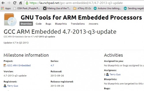
1. Download and install GNU Tools for ARM Embedded Processors (Win32 Release -- 2013, quarter 3).During the installation, make sure to check the box "Add path to environment variable."
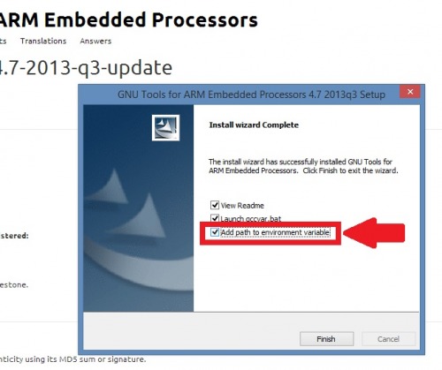
Check "Add environment variable."
If you missed this part, you can add a path to the environment variables by:
Right clicking on This PC / My Computer --> Properties --> Advanced system settings --> Environment Variables --> Select "Path" under "System Variables --> Edit. Go to the end of the list of paths, add a semicolon, then place the path of the GNU tools bin.
For me, this was " C:\Program Files (x86)\GNU Tools ARM Embedded\4.7 2013q3\bin "

We are going to add several paths to the path systems variables. So, refer back to these steps as needed.

2. Download Frank Duignan's Windows linker script , LPC1114 header file , and build batch file.
Ted Burke was nice enough to put these up for us. However, there's two pieces missing for us to use these amazing tools.
3. Create a workspace folder. e.g., "C:\Users\Ladvien\Documents\LPC1114_Bare_Metal".
4. Install binutils for file conversion. Binutils has to be compiled for Windows, though, I was able to find them pre-compiled.
Download Binutils compiled for Windows
Really, we are only using Binutils for objcopy , which is at the end of the batch file. This translates the .elf produced by the ARM compiler into a .hex file. To unzip Binutils file I'd recommend using 7zip . After installing them add the bin folder to your environment variable (see step 1). For me, I added " C:\Users\Ladvien\Documents\LPC1114_Bare_Metal\Ming32\bin".
5. Create a build script in a batch file.
Create a build batch file recommend by Duignan and Burke. Open your workspace folder, create a new text file, enter the following:
arm-none-eabi-gcc -mcpu=0 -mthumb -v -g -c init.c -o init.o
arm-none-eabi-gcc -mcpu=0 -mthumb -v -g -c main.c -o main.o
arm-none-eabi-ld init.o main.o -v -L "C:\Program Files (x86)\GNU Tools ARM Embedded\4.7 2013q3\lib\gcc\arm-none-eabi\4.7.4\armv6-m" -lgcc -T linker_script.ld --cref -Map main.map -nostartfiles -o main.elf
objcopy -O ihex main.elf main.hex
Save the text file in your workspace as "build.bat" Be sure to include the quotation marks, since this will convert the file from a text file to a batch file. This is the same build commands put together by Duignan, but I've added the "-v" option. This is the verbose mode and will spit out an errors during compiling.

6. Setup a C++ friendly text editor, like Programmer's Notepad .
7. Create a file called main.c in your workspace directory. Enter the following text:
/* Simple PWM demonstrator program
 * The program simply ramps the duty of pin 10
 * from 0% to 100%  and then resets back to 0%
 *
 */

#include "lpc111x.h"

void ConfigPins()
{
    SYSAHBCLKCTRL |= BIT6 + BIT16; // Turn on clock for GPIO and IOCON

    // Begin Port 0 setup.
    // Make Port 0 bit 5 behave as a generic output port (open drain)
    IOCON_PIO0_5 |= BIT8;
    // Make Port 0 bit 10 behave as a generic I/O port
    IOCON_SWCLK_PIO0_10  = 1;
    // Make Port 0 bit 11 behave as a generic I/O port
    IOCON_R_PIO0_11  = 1;
    // End Port 0 setup.


    // Make pin 10 behave as a PWM output CT32B1_MAT0
    IOCON_R_PIO1_1 |= BIT1 + BIT0;
}
void initPWM()
{
    // will use counter/timer CT32B1
    // Turn on CT32B1
    SYSAHBCLKCTRL |= BIT10;
    // Use match register 3 as period register because its output
    // is not pinned out.  A value of 48000000 produces a frequency of 1Hz
    // so, to generate a 30kHz pwm signal, set MR3 = 48000000/30000 = 1600
    TMR32B1MR3 = 1600;
    TMR32B1MR0 = 1600; // Zero output to begin with
    TMR32B1MCR = BIT10; // Reset TC on match with MR3
    TMR32B1TC = 0 ; // Zero the counter to begin with
    TMR32B1PWMC = BIT0; // Enable PWM on channel 0
    TMR32B1TCR = 1; // Enable the timer

}
void setDuty(int Duty)
{
    // sets the duty to the percent specified.
    // Need to 'invert' the requested duty as the PWM mechanism
    // resets the output at the start of each PWM cycle and then
    // sets it on match.
    TMR32B1MR0 = (100-Duty) << 4;
}
void delay(int dly)
{
    while(dly--);
}
int main()
{
    int Duty=50;
    ConfigPins();
    initPWM();
    while(1)
    {
        setDuty(Duty++);
        if (Duty > 100){
            for (Duty > 1; Duty--;){
                setDuty(Duty);
                delay(100000);
            }
        }
        delay(100000);
    }
}
Save the main.c file.
I've modified the above code from Duignan's to make it comparable to the Fade sketch in the Arduino examples.
8. Open the command prompt in your workspace directory. Run your build.bat file.
After running the build.bat, it should build five files: main.o, int.o, main.map, main.elf, main.hex. If it doesn't build correctly, double check the path variables for both the compiler and binutils.
We still have the problem of getting the main.hex uploaded to the LPC1114. You can use FlashMagic, like above, but I'm trying to stick to the command line, that's where lpc21isp comes in.
I've pre-built lpc21isp for Windows.
Download LPC21ISP (now with automatic mode switching! :)
But if this doesn't work for you, then you'll have to build it yourself .
10. Create a another batch file called, " LPC1114_upload.bat "
Only one line this time:
lpc21isp -wipe -localecho -hex main.hex COM3 57600 12000
You'll have to adjust the COM port to the port you are using. Here is a little bit of a guide using lpc21isp . Also, you'll either need to put the lpc21isp file in one of the folders added in the path variable. Or, make sure the LPC1114_upload.bat and lpc21isp files are in the same directory as your main.hex.
11. Wire up your LPC1114.

One last bit I should point out, when "DP24" is connected to ground and then voltage is supplied to the LPC1114, it'll enter the hardware bootloader. But, if DP24 is open or (preferably) pulled-up with a resistor when voltage is supplied to the LPC1114 then it'll run whatever code has been uploaded to the flash memory.
"DP24" is actually pin 1 on port 0.

12. Connect your LPC1114's RX/TX to an serial connector, put it into the bootloader mode by connecting DP24 to ground, then apply power to the LPC1114. Lastly, run the LPC1114_upload.bat file. This should result in the LED connected to "SWDIO" pin to fade on and off.
And that's what I've got. I'm going to start working on coding now, so I'll trade to add to this write-up as I've more to share. I plan to try these steps on my lab machine around June 1st to make sure they work. But if anyone uses them before them, please let me know if there are corrections to be made. As always, I value feedback and critique.
Update: FTDI Mode switching
The lpc21isp allows for automatic mode switching , that is, you can use an FTDI cable as below:

Then replace the line in your LPC1114_upload.bat file with
lpc21isp -wipe -localecho -control -hex main.hex COM3 57600 12000
This will automatically put the LPC1114 into program mode, upload your code, then reset to run your newly uploaded program. Just like Arduino! (Bdk6, you didn't see that statement, right? :)
Of course, lpc21isp is an agglomeration and had an error(?) that wouldn't reset the chip after downloading the new code. I simply commented an if-statement and it is now "working." I'm sure I've lost some robustness, but hell, it does what I want with no apparent side-effects. If you would like to know more about how I "broke" lpc21isp check my Github readme on the issue.
