I thought I’d take some time away from coding my LPC1114 Uploader and verbally process a few things I’ve learned. As always, feel free to critique any of it; it’ll only serve to make my code more robust in the end.
This post will be a series of post leading up to the large post I’ll make on writing the uploader. All posts will rely on the GCC compiler.
**
Setting Up the GCC Compiler**
I setup a C environment as basic I could. There may be easier ways to go about this, but I wanted to use GCC to compile.
As for editing, I’ve really grown to love Sublime Text 2.
If you have issues, make sure directory containing your files is in your PATH environment variable (I go over how to add the directory to your environment variables in this post).
Intel Hexfile to An Array Based on Data Address
To load data from an Intel HEX format file I used several functions, open_file() to create a data stream, more commonly know as a file pointer, from the file I wanted to read. And hex_file_to_array(), to parse the hex file and extract the data.
main.c
MAIN.Cintmain(intargc,char*argv[]){//If the user fails to give us two arguments yell at him.if(argc!=2){fprintf(stderr,"Usage: %s <readfile1>\n",argv[0]);exit(EXIT_FAILURE);}// Data arrayuint8_tHEX_array[32768];// Bytes read into array.intHEX_array_size;//File to be loaded.FILE*hex_file;//Open file using command-line info; for reading.hex_file=open_file(argv[0],"rb");// Load the data from fileHEX_array_size=hex_file_to_array(hex_file,HEX_array);}// END PROGRAM
6: Let’s check the number of arguments passed in by the user. If there is no file name, then we exit.
11: Declare a unsigned array for the data. I’ve set it arbitrarily, but it will need to be large enough for the amount of data to be extracted from the hexfile.
17: Here we create a pointer to a file data stream.
20: We pass the pointer to the data stream to the open_file function. We are setting up to only read the file in binary. We pass it the file we wish to open and it returns the opened file.
23: We pass hex_file_to_array a file pointer and pointer to an an array. This function reads the hex file, parses it, extracting the data and placing them into the the uint8_t array based on the data’s address found in the hexfile. The function then returns the number of data bytes found in the hex file.
open_file()
This function takes the name of a file and the mode under which to open it, then attempts to open a file pointer to this file. If it is is successful, it returns the pointer to the now open file. If it it fails, the program exits with an error code.
MAIN.C//Open file for reading, function.FILE*open_file(uint8_t*file,uint8_t*mode){FILE*fileOpen=fopen(file,mode);if(fileOpen==NULL){perror("Unable to open file");exit(EXIT_FAILURE);}returnfileOpen;}
To understand this function it pays to understand well the Intel HEX file format.
All of the information in the file is important, but we are only looking to put the Data into the array. To extract this data we are going to use three sub-routines:
read_byte_from_file()
Ascii2Hex()
clear_special_char()
read_byte_from_file()
One bit to understand about hex files is the data is actually stored as ASCII characters. When we open a file pointer to these ASCII characters, we can’t just read the bytes, since they’d simply be an ASCII character representing the nibble read. To make the conversion we get a character, store it as a binary nibble A, get another character and store it as binary nibble B. We then combine nibble A and B into a single byte.
The function takes three parameters: the file pointer, a uint8_t pointer for storing the complete byte, and the total_chars_read, which allows us to track how far we are into the file.
DATA.Cuint8_tread_byte_from_file(FILE*file,uint8_t*char_to_put,int*total_chars_read){//Holds combined nibbles.uint8_thexValue;//Get first nibble.*char_to_put=fgetc(file);clear_special_char(file,char_to_put,total_chars_read);//Put first nibble in.hexValue=(Ascii2Hex(*char_to_put));//Slide the nibble.hexValue=((hexValue<<4)&0xF0);//Put second nibble in.*char_to_put=fgetc(file);clear_special_char(file,char_to_put,total_chars_read);//Put the nibbles together.hexValue|=(Ascii2Hex(*char_to_put));//Return the byte.*total_chars_read+=2;returnhexValue;}
6: Declaring a 8-bit unsinged integer to hold the finished byte.
8: Get an ASCII character from the file pointer.
9: Here we call the cleaer_special_char function to remove ‘\n’ and ‘\r’ found in the hex file.
11: We then convert the ASCII character into a true binary nibble. The result is stored in the string. (I will cover the Ascii2Hex function below.)
The above steps are repeated for nibble B.
18: We combine the string of nibbles into a byte.
26: We increment two ASCII characters read from the file pointer.
clear_special_char()
The clear special character function is simply meant to remove the ‘:’, ‘\n’, and ‘\r’ characters from the data stream. It simply looks through the character pulled from the data stream. If it is not a special character, it does nothing. If it is, it increments the character counter and discards the character.
Another fairly simple function. Here, we simply find the numeric value of the ASCII character and convert it to its binary equivalent.
DATA.C//Copied in from lpc21isp.cuint8_tAscii2Hex(uint8_tc){if(c>='0'&&c<='9'){return(uint8_t)(c-'0');}if(c>='A'&&c<='F'){return(uint8_t)(c-'A'+10);}if(c>='a'&&c<='f'){return(uint8_t)(c-'a'+10);}return0;// this "return" will never be reached, but some compilers give a warning if it is not present}
This function is pretty simple, if you keep in mind each character is actually an integer. For example, the if-statements could be re-written as follows,
You can use an ASCII reference table to determine how a character read will be interpreted. For instance, ‘D’ or ‘d’ would be 68 or 100. 68 - 65 + 10 = 13. We know D is hexadecimal for 13 (0 = 0, 1 = 1, 1 = 2, etc… A = 10, B, = 11, C = 12, D = 13, E = 14, F = 15).
This brings us to the main function,
read_line_from_hex_file()
DATA.Cboolread_line_from_hex_file(FILE*file,uint8_tline_of_data[],longint*combined_address,int*bytes_this_line){intdata_index=0;uint8_tchar_to_put;inttotal_chars_read=0;//To hold file hex values.uint8_tbyte_count;uint8_tdatum_address1;uint8_tdatum_address2;uint8_tdatum_record_type;uint8_tdatum_check_sum;//BYTE COUNTbyte_count=read_byte_from_file(file,&char_to_put,&total_chars_read);// No need to read, if no data.if(byte_count==0){returnfalse;}//ADDRESS1 //Will create an 8 bit shift. --Bdk6'sdatum_address1=read_byte_from_file(file,&char_to_put,&total_chars_read);//ADDRESS2datum_address2=read_byte_from_file(file,&char_to_put,&total_chars_read);//RECORD TYPEdatum_record_type=read_byte_from_file(file,&char_to_put,&total_chars_read);// No need to read, if not data.if(datum_record_type!=0){returnfalse;}*combined_address=((uint16_t)datum_address1<<8)|datum_address2;// DATAwhile(data_index<byte_count){line_of_data[data_index]=read_byte_from_file(file,&char_to_put,&total_chars_read);data_index++;}*bytes_this_line=data_index;// CHECKSUMdatum_check_sum=read_byte_from_file(file,&char_to_put,&total_chars_read);returntrue;}
The above code parses exactly one line of hex data from the file pointer.
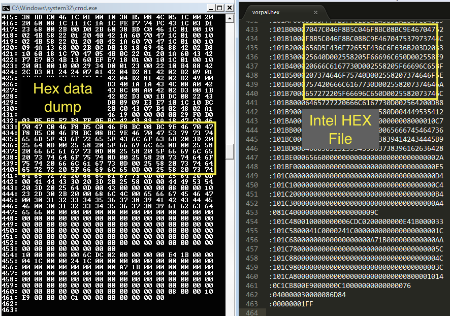
17: We read the first byte of a line. This should be the ‘:’ character, but remember our clear_special_char() should skip this and read the next two bytes ‘1’ and ‘0’ (green). The “10” is how many bytes of data (blue) found on this line. Note, 10 is not a decimal number, it’s hexadecimal. Meaning, there should be 16 bytes of data found on this line.
20: We check if there was any data on this line. If there are zero data, we return false.
23: Take the first byte of the data address (purple).
26: Take the second byte of the data address (purple).
29: Get the byte (red) identifying the type of information found on this line. We are only looking for data (‘00’). The other types are explained well at the ole’ Wiki article: Intel HEX record types.
32: If the record type is not data, we don’t want it. We return false.
34: Combine the two 8-bit address bytes into one 16-bit address.
37: Let’s get all the data found on this line and put it into the array we provided the function.
42: We have to keep track of how many bytes are on each line, to complete our address of the data. Therefore, we pass it back to hex_file_to_array().
45: I read the checksum, but I don’t do anything with it. I probably should.
hex_file_line_count()
To properly parse the hexfile we need to know how many lines are found in the the file. We can find this information several ways, but I counted the number of line start characters ‘:’.
8: Loops until the end-of-file character is reached.
10: Gets a ASCII character from the file pointer.
11: We check to see if the character we go was line start character ‘:’.
13: This function iterates through the entire file, but we want to start pulling data from the beginning of the file, so we rewind the file to the first character.
14: We return the number of lines.
hex_file_to_array()
DATA.Cinthex_file_to_array(FILE*file,uint8_thex_data[]){// 1. Get line count.// 2. Read a line. From ':' to '\n'// 3. Parse a line.// Repeat for all lines.// Data per line.uint8_tline_of_data[32];longintcombined_address[4096];// Indices and countersinthex_line_index=0;intchars_this_line=0;inttotal_chars_read=0;// How many lines in the hexfile?inthex_lines_in_file=0;intbytes_this_line[4096];// Let's count how many lines are in this file.hex_lines_in_file=hex_file_line_count(file);// Indices for parsing.intline_index=0;intbyte_index=0;boolread_line_ok=false;// Parse all lines in file.while(line_index<hex_lines_in_file){read_line_ok=read_line_from_hex_file(file,line_of_data,&combined_address[line_index],&bytes_this_line[line_index]);if(!read_line_ok){printf("Line#: %i. Dude, that's not data!\n",line_index);read_line_ok=true;}while(byte_index<bytes_this_line[line_index]){hex_data[combined_address[line_index]+byte_index]=line_of_data[byte_index];line_of_data[byte_index]='\0';byte_index++;}byte_index=0;line_index++;}// Print out parsed data.intk=0;intj=0;intprinted_bytes=0;while(k<hex_lines_in_file){while(j<bytes_this_line[k]){printf("%02X ",hex_data[j+(printed_bytes)]);j++;}printed_bytes+=bytes_this_line[k];j=0;printf("\n");k++;}returntotal_chars_read;}// End hex_file_to_array
23: We count the number of lines in the file we wish to extract data.
31: This is the work-horse loop. We loop until the we have read through all the lines we counted.
33: We pass read_line_from_hex() our variables we wish to fill. The hex file we want to parse (file), the buffer we hold the line data in, the int array which will serve to hold the address of this line of data, a variable to hold the number of bytes in this line. If the function was got data, it will return true. Otherwise, it will return false. We store this flag to make sure we got something.
34: We check to see if we actually got data from our attempt.
39: Here, we move the line of data from the buffer into the final array.
41: We place the data into the array based upon the address we pulled from the line (address1 + address2) and the byte number.
42: Reset the buffer to nil.
49-64: Finally, we print out the data. The k-loop goes through each line we extracted; the j-loop goes through each byte found on the respective line.
And that’s it. Note, 49-64 is meant to demonstrate the data is properly extracted. These lines could be moved to another function where the data may be used as needed.
This toolchain is amazing. Really, if you are wanting to break away from Arduino / AVR, into the ARM chips, Bdk6’s toolchain for the LPC1114 is the way to go.
The Valdez Mutant v04
The chip has ROM boot loader. This allows you to program the chip right out of the box. The programming is done over the traditional serial line. Most ARM chips require a JTAG programmer, which are usually a $50 investment. This leads into a few of my design goals.
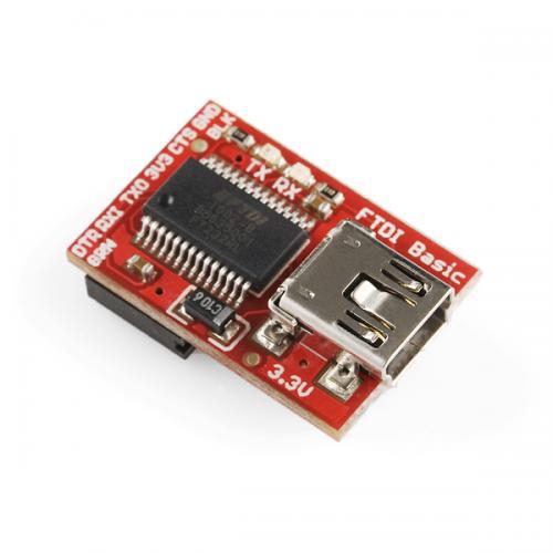
A-2. Arduino Pro Mini (APM) FTDI programmer to program the LPC1114
After doing a bit of AVR programming I toyed with the idea of getting into the Atmel ARM chips. One barrier to entry is cost, and now that we are down to one income this is a Hannibal to Rome grade barrier. Not only were most of the chips in the $6-20 range, they required a JTAG connector to program. Ultimately, price kept me from building a board around an Atmel ARM chip.
But then Mr. Bdk6 introduced me to the LPC1114. Not only was the chip sub $3 in single quantities (cheaper than the Atmega328P), but it was also programmable with a typical serial-USB interface. I figured, if it was programmable by serial then I could program it with my Arduino Pro Mini FTDI Breakout, which I bought from SparkFun long ago. I did this selfishly, but I assumed a lot of Arduino roboticists here have also switched to the APM as their go to board. I further assumed most would probably have a APM FTDI connector. I took this into account because my goal was to reduce as many barriers in switching from Arduino to the LPC1114, short of writing simple and opaque support libraries.
I’m going to take a brief moment and explain the LPC1114’s ISP ROM. The LPC1114 has a built in bootloader, which resides in a ROM block on the chip. When the chip is provided power, either on initial or reset, it runs this bootloader. The bootloader polls PIN 1 on PORT 0 (PIO0_1), if this pin is high or floating, then the bootloader executes whatever is in the program memory blocks. If PIO0_1 is low, then the LPC1114 enters in-system programming mode.
When I discovered this, I got excited. Why not use the DTR/CTS pins to control the ISP? I added it to my design goals.
A few problems:
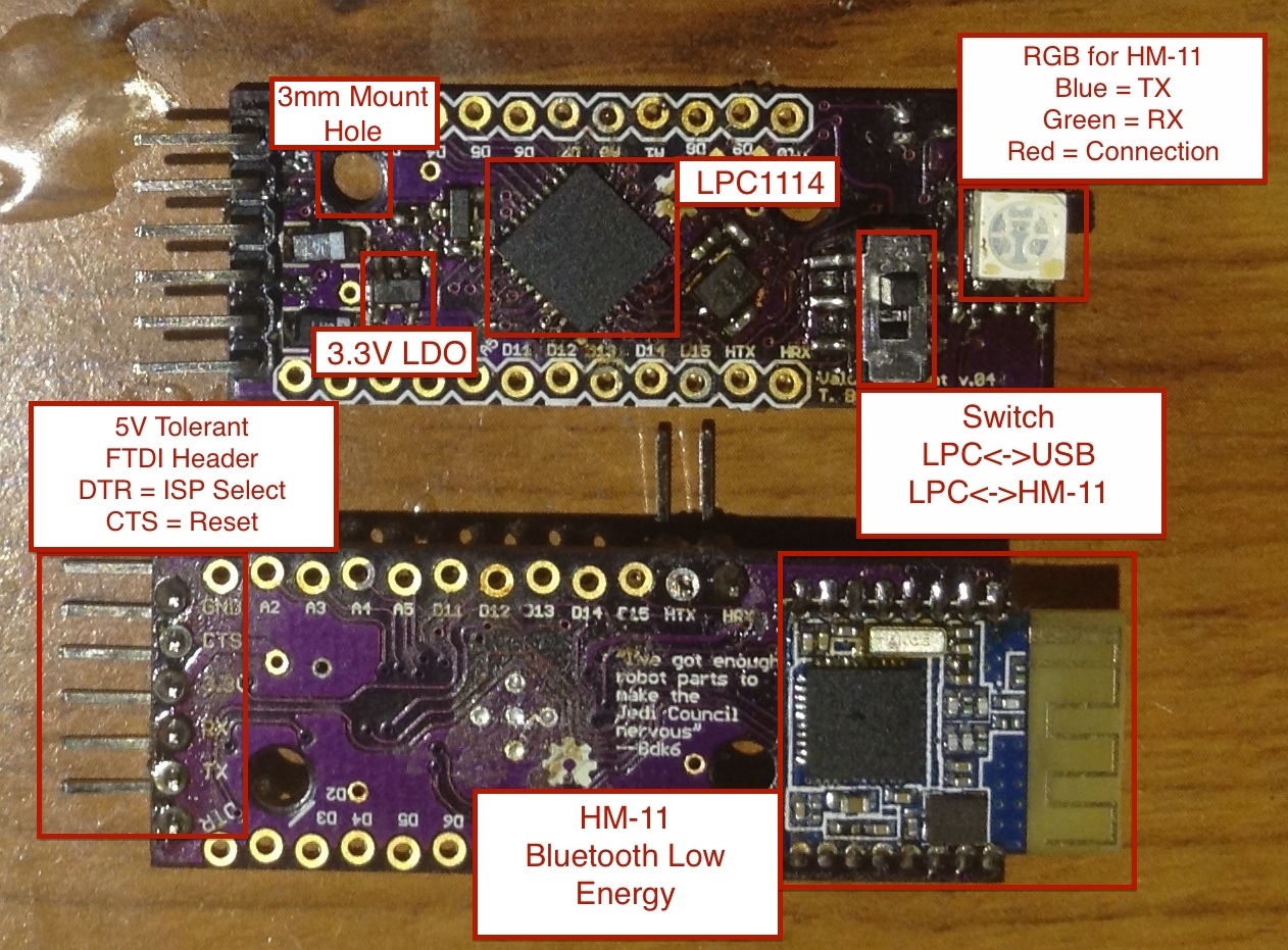
1. The LPC1114 operates on 3.3v. And don’t let your “3.3V” FTDI breakout fool you. They still spit out 5V on for VCC, RX, and TX, at least until you jumper the solder-jumper on the underside. No sweat, I’ll add a logic-level translator.
2. There is no existing LPC1114 programming software that controls DTR/CTS.FlashMagic and lpc21isp both use DTR/RTS, while the APM FTDI breakout I have uses DTR/CTS. Stupid dung-beetles in the ointment. I was committed to the idea of using the APM FTDI connector as a “no-modification” way to program the LPC. Thus my toils began.
I started by trying to change the source of the lpc21isp. I was successful in manipulating the source, but the lpc21isp relies on Windows communication protocol drivers, which don’t allow for the bit level control of the CTS pin. Damnit.
Still committed.
I started re-rolling my own bootloader using FTDI drivers, which do allow for bit level control of all pins (FTDI Bitbanging). Sadly, I got distracted by writing a iPhone app for the HM-10. By the time I finished the app, Bdk6, who heavily guided me on how to re-roll the programmer, stated he was writing one and would attempt including the features I requested. I figure, “I think this is one time being lazy is in the best interest of everyone.” I let Bdk6 write the programmer. :)
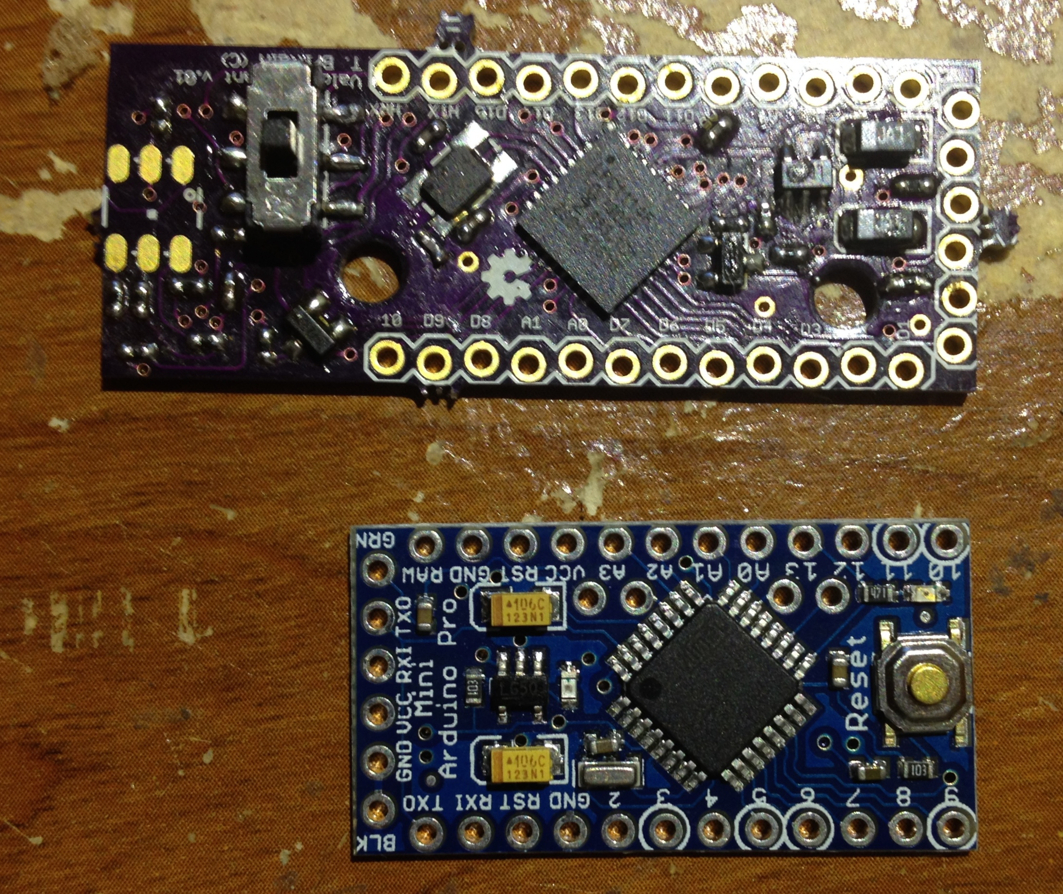
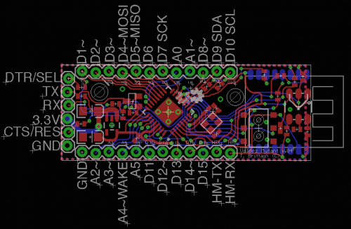
A-3. _Almost _the same size as the Arduino Pro Mini, but with Mounting holes.
I love the Arduino Pro Mini (APM) for robot building. It is small, powerful, robust, it’s just good stuff all around. When I decided to build an LPC board I wanted it to copy it in design.
Here are the features I pulled:
1. All components are on one side (except for the HM-11). This allows for easy reflow.
2. Small. The Valdez Mutant is the same dimensions as the Arduino Pro Mini, except for the “diving board” area where the HM-11 sits. APM is 18x33mm and the Valdez Mutant is 18x46.97mm
Features lost:
1. I didn’t put a reset switch. I was banking on the BLE being able to reset the HM-11 serially (I’ll get to that in a bit).
2. A power LED. I decided the RGB LED blinking for the HM-11 could double as a power-led, since the power-rail is the same for the HM-11 and the LPC1114
I added one feature that I’ve always felt the APM was lacking: Mounting Holes. Some time ago I realized as I continued challenging myself to make smaller and smaller PCB solutions, there gets a point where the board is too small to easily work with. The connecting wires hold it in the air, or pull it off where you set it. I decided I’d add 3mm mounting holes to hold my board in place.
A-4. Wireless Programming Over BLE.
I’ve always dreamed of hooking up a Bluetooth module to an Arduino and uploading sketches wirelessly. When I discovered the HM-10 I thought I had a real chance (I’ve not completely given up on the idea), but it took editing the Arduino IDE source. I was able to tweak and compile it, but if anyone who has been through the Arduino IDE source will tell you, it’s a friggin mess. But when I went over the design of the LPC programmer interface, I realized the process of flipping bits on the ISP SELECT and RESET lines with the FTDI could be done remotely by the HM-10, using the PIO pins. Hmm. Light bulb.
I therefore set out to design a board that would allow for wireless uploading of programs.
Instead of using my traditional go-to HM-10, I decided to switch it up and attempt using the HM-11.
The HM-11 is pretty much the same board as the HM-11, but instead having the 8 or so IO pins, it only has 2. Perfect. One for RESET and one for SELECT.
I thought the HM-11 would allow me to stay consistent with design goal #3: Itty-Bitty.
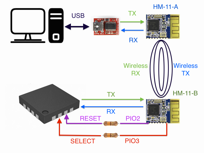
In theory, this is how the wireless uploading would work.
HM-11-A sends “AT+PIO30”
The HM-11-B PIO3 will go low, which sets the LPC1114 ISP MODE to LOW.
HM-11-**A **sends “AT+PIO20”
Then, the HM-11-B PIO2 goes LOW for ~5uS. This will reset the LPC.
As the LPC comes back up it checks the ISP MODE pin and sees it LOW.
HM-11-**A **sends “AT+PIO31” waits ~100mS then sends “AT+PIO21”
The HM-11-B PIO3 and PIO2 will go HIGH.
The LPC enters ISP mode.
The HM-11 PIO2 & PIO3 go HIGH.
The program is uploaded to the LPC.
HM-11-**A **sends “AT+PIO20”
HM-11-B PIO2 goes LOW, resetting the LPC.
HM-11-**A **sends “AT+PIO21”
HM-11-**B **PIO2 goes HIGH and the LPC runs the uploaded program.
B-1. Testing
Testing this board was a bit of a bitch. The first version (v02) I printed had several major flaws:
Mistakes on 1st iteration:
The RX/TX lines were flipped (I swear, I never get that right).
The CONN pin on the HM-11 was wrong.
I routed the CTS pin to pin PIO02, which is _not the reset pin.
There was a N-Chan flipping for the HM-11 to flip the LPC power. I got rid of that and simply ran a line to the reset (duh).
I quickly corrected these problems and sent the board off again. When the 2nd Iteration came in I wasn’t able to test it. No matter what I did I couldn’t get it to go into ISP mode. I got pretty harsh on myself, blaming my “crappy soldering skills and dellusions of ability.” Then it hit me, I had added 10uF and those take a bit to discharge. I threw the multi-meter on it and sure enough, when I pulled the power from the LPC, then reapplied it (I was using this method instead of the reset line) it took a good 30 seconds for the voltage to drop near nominal. I quickly strung up a momentary switch on the reset line, first time I hit the button it went right into ISP mode. Son-of-a-badger!
Therefore, I consider the 2nd iteration a hardware success.
But there was a big let down. I tried both FlashMagic and lpc21isp to get them to upload across the BLE connection, but they both timed out. Ugh. I guess no wireless download?
Features tested:
FTDI pinout – Working – 50% tested – (works to provide power and RX/TX work, ability to reset and select mode not yet tested. This will require customer software).
5v/3.3v RX/TX converter – 100% tested – Working
DPDT Switch to select HM-11 or USB – 100% tested – Working
Crystal – not yet tested 0%
HM-11 – RX/TX – 100% tested – Working
RGB TX/RX/CONN – 33% tested – CONN Working
LPC reseting HM-11 – not yet tested 0%
HM-11 controlling RESET and ISP MODE – not yet tested 0%
Board Tested and Working: 48%
B-2. Support and Design Files
I’m a hack. I wouldn’t even be hacking with LPC1114 if it weren’t for the support tools put together by Mr. Bdk6.
Alright, so now what? Um, let’s build a robot with it. To do this, I’m going to design a motor PCB with the DRV8837. And I’m hoping that Mr. Bdk6 doesn’t mind adding the FTDI reset features and the HM-11 upload features. If he doesn’t have time, then I’ll probably pick back up my attempt to write my own bootloader.
I did notice a few problems. First, I didn’t allow for a VIN pin. This means I’m going to have jumper between a “shield” board and the Mutant. Also, I’m worried about fitting two H-bridges on a PCB as small as the Mutant, the DRV8837 is very small, but the traces to it take a lot of real-estate.
Well, that’s it.
A huge thanks to Mr. Bdk6. These tools are amazing; finally escaping Arduino!
(This node will probably float a bit, have lots of work to do on it. My apologies.)
I’d been wanting to create a bridge between Arduino and iOS for awhile. Not going to lie, not a huge fan of iOS devices, but since my wife won an iPad Mini I’ve begrudgingly accepted they fill a need. Still, my hacking has orbited robotics and any device I can’t connect to a robot frustrate me. Well, a year ago I realized an iPad Mini would connect to an HM-10, and therefore, robot.
Sadly, the app used to connect to the HM-10 was LightBlue, an app with little versatility. However, it allowed me to confirm everything was in place to the connect the iPad Mini and a robot. Of course, I wasn’t willing to pay several hundreds of dollars at the chance I could develop an app. Well, the idea got filed under “NSF.”
But, two months ago I was contacted by Simon Riley, the CEO of Carduino. He asked why I had stopped short of developing an iOS app to interface with the HM-10 BLE Serial modules. My response was short: Lack of funds. I explained to develop in iOS (legally, and therefore weary and worry free) you need an iOS developer’s license and a Mac to develop from; I hadn’t money for either. Simon responded the next day, “Maybe we can help with that.”
Long story short, Carduino donated to the cause and I used my robot allowance (you married guys understand) to purchase the rest. So, what did I get?
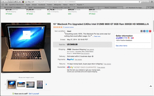
Mac Mid 2009
Price ended at $469.99. I spent a little more than I should, but since Carduino had added to the kitty I was worried about getting something I’d be unable to run Xcode. Therefore, I spent a little extra in hopes to get a machine that would allow me to write code efficiently.
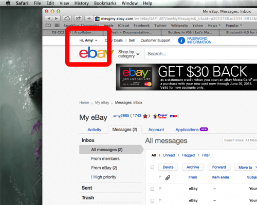
I have to take a moment and remind people, I wear a white hat. Dear Amy2865, before you sell a laptop, be sure to log out of your eBay account. Also, Jared Kusma, I’m liking your laptop, but I _did _clean the keyboard thoroughly before using it. And the spots on the screen.
Alright, enough of the teasing. Moving on.
I deal with clinical delusions. But, I’m learning to force them to serve me. I realize I’ll never be as good as I feel in the throes of a delusion. Yet, I’ve allowed these words to guide me,
Believing I can do anything, may not be true. But believing it is enables me to do_ almost_ anything.
Well, when I accepted Carduino’s funds to help develop an app I might have been delusional. I didn’t tell anyone I’d never used a Mac before, let alone wrote Objective-C. But one thing I believed, if I determine myself to do something I will. Of course, my timeframe is my own and the product might be apparently hackish, but it will get done.
Anyway, I admittedly had no idea what I was doing, so I decided to journal as I went.
This brings me to my disclaimer:
I am not a professional programmer. I do not pretend to be. With that, please feel free to point out my mistakes, inefficiencies, or ineffective code in general. Part of the reason I post articles like this is for the peer-review. But don’t expect me to apologize much for stuff I didn’t catch. Working a full-time job in a non-tech field, having a wife in graduate school, raising a four-year-old, well, these things leave me little time to program, and nearly no time for code review.
I don’t think there are mistakes in my code, I know there are. Alright, self-deprecation aside, let’s get going.
1. Setting up the Environment
First, you need a Mac and a Developer’s License. The Mac really needs to be at least 2008 or later to effectively code for the current iOS (7.1 at writing, 8.0 being in beta).
After looking over many “deals” on eBay I decided on a Mac Book Pro 2009. It seemed old enough people didn’t have an unhealthy attachment. Later than 2009, it was like people were selling their pretty daughter.
I chose the Mac Book over Mac Mini. The Mac Book came with a monitor and peripherals. Maxhirez warned me some Mac Mini’s have proprietary video out, which would force me to buy a monitor as well.
I was a a lot worried an eBay Mac would be DOA. When it finally came in, I was relieved to see it boot up. But, within an hour it overheated and crashed. Worried the crap out of me. I then realized this laptop had two video cards and the display settings were full-blast. I backed down the video settings and the temperature seemed to hold. Still a little worried. When I get the app written for Carduino I’ll probably take it apart, clean the heat-sink fins and reapply thermal paste.
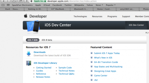
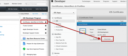
If you try to compile your app and youget an error regarding a certificate, and doesn’t automatically resolve, you can download a certificate manually.
Download Developer certificate
1. Log on to iOS Dev Center and Download you Developer Certificate
You will need to apply this certificate to the apps you write to publish them–even on an ad hoc basis.
2. The App We’ll Write
This write-up describes writing an app for Bluetooth 4.0 iOS devices to enable a serial connection to an Arduino. To facilitate the serial connection on the Arduino-end a HM-10 acts as a peripheral, which in turn, interacts with the Ardunio via a serial connection.
The HM-10 operates on 3.3v and the Arduino 5v, but I created an Instructable on how to convert the HM-10 to 5v.
Before I started this projects I’d never used a Mac, never seen Xcode 5, let alone looked at Objective-C code. But, like the delusional man I am, I thought, “Well, it’s got the word ‘C’ in its name; couldn’t be that hard for me to learn.” Stupid me.
Objective-C is silly. Well, I shouldn’t say its entirety is silly; the verbosity and syntax are silly, though. The idea being everything is spelled out, nothing abbreviated, which makes the code chewy to read. Anyway, I’ll stay away from psychological rants about brevity being the essence of wit. Or how humans will psychologically gravitate towards messages easy to encode and decode.
This article isn’t going to go into much on how to write Objective-C or use Xcode, since there are already many excellent guides.
His written tutorials are free, but giving the visual component of Xcode I paid $15 for a subscription to his video tutorials. Both written and video tutorials are excellent. Learned pretty much everything I needed from him and his peers.
I would list other tutorials, but really, Ray’s covers everything you’d need to write this app–well, besides the Bluetooth part, which I’ll cover. But one surprisingly helpful video was Apple’s introduction toCoreBluetooth Framework.
The app we’re going to write is pretty simple. Really, it is. It takes the values from two Slider Controls and sends them via Bluetooth to an Ardunio. The Arduino in turn converts these values into direction and PWM values for two wheeled-motors.
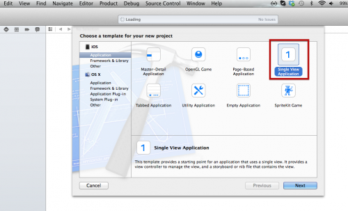
Ok, open Xcode and let’s start a new projects. We are going to use a Single View projects.
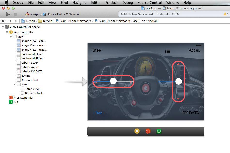
The first step in creating our app will be laying out the user interface. This boils down to a few items.
View for Background Image:
3 x Labels – Steer Value, Acceleration Value, RX Data
2 x Buttons – TEST Send and Scan Devices Menu Button
1 x View – Acts as a hideable container for scanned devices.
The Scan Devices View will act as a container for the Devices Table View. We will set its initial state to hidden and then reveal it programmatically triggered by the Devices Menu Button.
Just download the projects as zip. Then, within the projects there is another zip titled: bleAppStartLayout.zip Simply unzip this projects and open it in xCode if you’d like to write your own code to go with the skeleton layout.
5. Code
There are three parts to the code of our app.
Code to control…
The Bluetooth connection
User interface
Devices List
In this article I’m only going to cover the Bluetooth code in depth. The rest is either pretty straightforward
Objective-C Bluetooth Code (and some UI):
Before we get going, it’ll help to be slightly familiar with Bluetooth 4.0’s standards and protocols. Also, iOS’ recommendations on using CoreBluetooth, Apple’s API for Bluetooth 4.0 hardware.
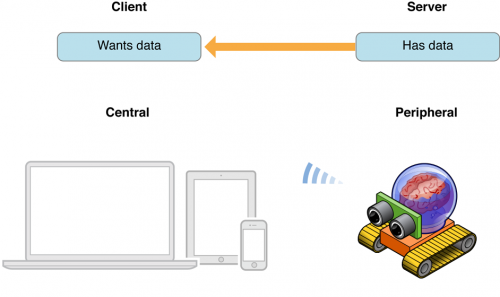
The big take away for us is the differences between Central and Peripheral roles.
This doesn’t mean our bot cant receive data or iOS device can’t send data, it simply defines the relationship between the devices. The role decides which device controls the connection and data flow. For the sake of this app thebot will be setup as a Peripheral and theiOS device will be the Central. This is my opinion, but it seems the BLE hardware connected to the uC or CPU with the greatest speed should take the Central role.
The header file – bleApp.h
To access the Bluetooth 4.0 functionality of compatible iOS devices, Apple provide the CoreBluetooth Framework. This framework is brought into your app code in the typical C fashion, by importing it inbleApp.h
#import <CoreBluetooth/CoreBluetooth.h>
Once the framework is imported we have access to the API methods.
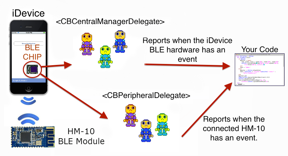
Alright, I’m going to attempt explaining something I poorly understand, Objective-C Delegates.
I believe a delegate is a collection of services your code can subscribe. I think of them much like interrupts in Arduino. Each time a specific event happens a method is called. You setup the delegates you wish to subscribe at the top of yourbleApp.h:
Here we are calling on subscribing to four delegates:
CBPeripheralDelegate
CBCentralMAnagerDelegate
UITableViewDelegate
UITableViewDataSource
The CoreBluetooth Central Manager, the CoreBluetooth Peripheral, User Interface Table View Delegate, and the User Interface Table View Data Source. Right now we are only going tofocus on the Bluetooth delegates.
Another way to think of delegates is a collection of little scout robots who report when a specific event takes place.
These delegates are a collection of little methods who will be called at specific events. For example, the CBPeripheralDelegate has the method-(void)peripheral:(CBPeripheral *)peripheral didDiscoverServices:(NSError *)error. This method is called whenever iOS app discovers BLE peripheral. Again, these methods areevent driven–this means something usually has to happen before the come report to your code.
Here are the major methods we will be using to control the iOS BLE hardware:
Next, we declare the properties we will need. If you know as little about Objective-C properties as I did here’s a good tutorial.
//// ViewController.h// Carduino//// Created by Ladvien on 6/21/14.// Copyright (c) 2014 Honeysuckle Hardware. All rights reserved.//#import <UIKit/UIKit.h>
#import <CoreBluetooth/CoreBluetooth.h>
@interfaceViewController:UIViewController<CBPeripheralDelegate,CBCentralManagerDelegate,UITableViewDelegate,UITableViewDataSource>// Instance of Central Manager.@property(strong,nonatomic)CBCentralManager*centralManager;// Stores a list of discovered devices, the key being their UUID.@property(strong,nonatomic)NSMutableDictionary*devices;// Instance method, used to act when a peripheral is discovered.@property(strong,nonatomic)CBPeripheral*discoveredPeripheral;// Instance method, used to act when a peripheral is selected to connect.@property(strong,nonatomic)CBPeripheral*selectedPeripheral;// Holds UUIDs.@property(readonly,nonatomic)CFUUIDRefUUID;// Stores peripheral characteristics.@property(strong,nonatomic)CBCharacteristic*characteristics;// Stores the advertising data of a peripheral.@property(strong,nonatomic)NSMutableData*data;@end
That should be all the code we need in our header file.
bleApp.m – Our Implementation
1. The UI Connection
Objective-C operates under the Modal-View-Controller design modal. We don’t have to go too deep into this design theory to be dangerous, the main thing we want to take away is UI elements are connected to our code with keywords. For UI elements we wish to change programmatically we set aIBOutlet and for UI elements we wish to generate an action we use the-(IBAction) methods.
An example of using an IBOutlet would like this:rxLabel.text = @”Got data”;
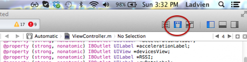
All good, now how do we make IBOutlets and IBActions? First, click on the “Tuxedo” button
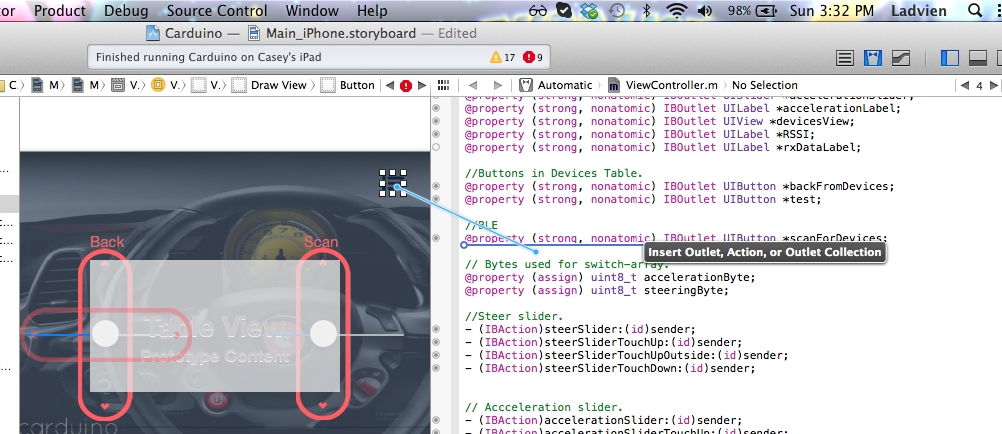
Now, hold CONTROL and click on the UI element you want to create an Action or Outlet, then drag to your code between@interface and@end.
Ray Wenderlich’s tutorials explain this process well. So, I wont rehash. A couple hints though, you can type out each of the IBOutlets and IBActions, but unless the dot on the bar next to where it is written is filled in, it is not connected to an element. Also, if you hover your mouse over the little dot while in tuxedo-view, the element it is connected to will be highlighted.
Ok. So, we need to connect up all of our UI elements. I’ll simply refer back to my video on the layout. Or I suggest you use the skeleton bleApp layout, since I’ve already wired up the UI elements.
Either way, we need to end up with code that looks something like this:
#import "ViewController.h"
@interfaceViewController()// Timers.@property(nonatomic,retain)NSTimer*steerSliderRecoilTimer;@property(nonatomic,retain)NSTimer*accelerationSliderRecoilTimer;@property(strong,nonatomic)IBOutletUITableView*tableView;//Outlets.@property(strong,nonatomic)IBOutletUIView*mainView;@property(strong,nonatomic)IBOutletUILabel*steerLabel;@property(strong,nonatomic)IBOutletUISlider*steerSlider;@property(strong,nonatomic)IBOutletUISlider*accelerationSlider;@property(strong,nonatomic)IBOutletUILabel*accelerationLabel;@property(strong,nonatomic)IBOutletUIView*devicesView;@property(strong,nonatomic)IBOutletUILabel*RSSI;@property(strong,nonatomic)IBOutletUILabel*rxDataLabel;//Buttons in Devices Table.@property(strong,nonatomic)IBOutletUIButton*backFromDevices;@property(strong,nonatomic)IBOutletUIButton*test;//BLE@property(strong,nonatomic)IBOutletUIButton*scanForDevices;// Bytes used for switch-array.@property(assign)uint8_taccelerationByte;@property(assign)uint8_tsteeringByte;//Steer slider.-(IBAction)steerSlider:(id)sender;-(IBAction)steerSliderTouchUp:(id)sender;-(IBAction)steerSliderTouchUpOutside:(id)sender;-(IBAction)steerSliderTouchDown:(id)sender;// Accceleration slider.-(IBAction)accelerationSlider:(id)sender;-(IBAction)accelerationSliderTouchUp:(id)sender;-(IBAction)accelerationSliderTouchUpOutside:(id)sender;-(IBAction)accelerationSliderTouchDown:(id)sender;// Menu-(IBAction)menuButtonTouchUp:(id)sender;@end
1. CBCentralManager
Ok, let’s get our Bluetooth going. Objective-C has a method that runs once if the UI loads,-(void)viewDidLoad method.
-(void)viewDidLoad{[superviewDidLoad];// Allocates and initializes an instance of the CBCentralManager._centralManager=[[CBCentralManageralloc]initWithDelegate:selfqueue:nil];}
We will add more code in this method later, but for now this will work. Here, we are simply allocating and initializing an instance of the CBCentralManager object. It has two arguments,initWithDelegate, we set this to self and the queue we set to nil. This allows us to inherit the CBDelegate from the ViewController.h. The queue being set to nil simply means we are going to allow the CentralManager to manage our data.
centralManagerDidUpdateState
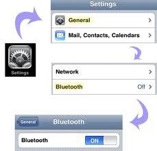
This method is called each time the BLE hardware on the iOS device changes state. Here, we are using it to check if the iOS’ Bluetooth hardware has been turned on.
ThecentralManagerDidUpdateState is a method called by the CoreBluetooth (CB) Central Manager Delegate whenever the BLE hardware in your device changes state. Here, it is being called when our app first begins. It will also be called each time the iOS Bluetooth is turned on or off.
// Make sure iOS BT is on. Then start scanning.-(void)centralManagerDidUpdateState:(CBCentralManager*)central{// You should test all scenariosif(central.state!=CBCentralManagerStatePoweredOn){// In case Bluetooth is off.return;// Need to add code here stating unable to access Bluetooth.}if(central.state==CBCentralManagerStatePoweredOn){//If it's on, scan for devices.[_centralManagerscanForPeripheralsWithServices:niloptions:nil];}}
The central.state property is set by the CBCentralManager Delegate. It has six states:
CBCentralManagerStateUnknown – Device can’t be read, etc.
CBCentralManagerStateResetting – Device is resetting
CBCentralManagerStateUnsupported – this device doesn’t support BLE.
CBCentralManagerStateUnauthorized – Your app isn’t authorized to use BLE
CBCentralManagerStatePoweredOff
CBCentralManagerStatePoweredOn
We will only be using the last two states. Our code checks if the BLE hardware is enabled; if it is not, it does nothing. Eventually, I’ll probably add an alert to notify the user, but right now, it does nothing. If the hardware is enabled, then it executes the centralManager instance method with two argumentsscanForPeripheralsWithServices: nil andoptions: nil.
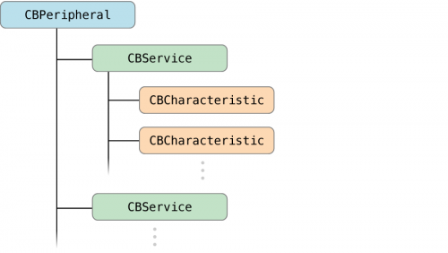
In case you didn’t have time to read the BLE protocol manual, I’m going to give you a crash course. Let’s start with the service tree. The magic of Bluetooth lies in its advertisment protocol. The Central BLE device is scanning the air, while the Peripheral is advertising its information. The information advertised coordinates services the peripheral device has available.
If you have a minute, Ada has an excellent article on Generic Attribute Profile (GATT) written by Keven Townsend (I like his stuff).
Keep two things in mind, first, I’m still learning what the hell I’m talking about. Two, jnhuamao and I have a history. I’ve watched their BLE firmware develop over the years. When the first procuded the HM-10, it didn’t conform to any BLE protocols. Now, they’ve got a damn fine product. Of course, they seem to be trying to get old school Bluetooth thinking to fit BLE. For instance, they equate the “Master” role of their modules with Central role protocol. Likewise, they equate “Slave” with Peripheral role. This confuses me a little, since
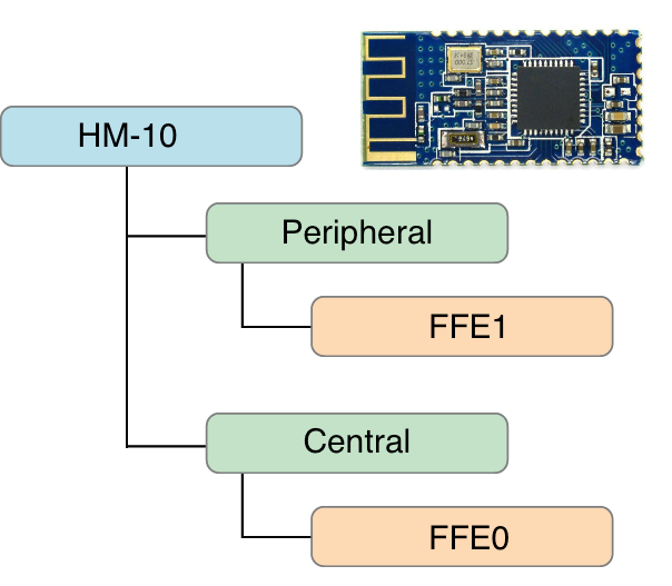
For the HM-10 it looks something like this,
When iDevice scans the HM-10 it’ll report back the FFE1 characteristic, which is the characteristic address for RX/TX on the HM-10.
**
**
centralManager didDiscoverPeripheral
The centralManager didDiscoverPeripheral method executes every time a new service has been discovered. It provides several bits of information about the discovered peripheral. First, the peripheral information itself, this includes its name, UUID, etc. Further information can be pulled from the advertisementData dictionary. Lastly, which is a neat attribute of BLE, you can access the RSSI of the discovered device before ever connecting.
// Report what devices have been found.-(void)centralManager:(CBCentralManager*)centraldidDiscoverPeripheral:(CBPeripheral*)peripheraladvertisementData:(NSDictionary*)advertisementDataRSSI:(NSNumber*)RSSI{// Set peripheral._discoveredPeripheral=peripheral;// Create a string for the discovered peripheral.NSString*uuid=[[peripheralidentifier]UUIDString];if(uuid)//Make sure we got the UUID.{//This sets the devices object.peripheral = uuid[self.devicessetObject:peripheralforKey:uuid];}//Refresh data in the table.[self.tableViewreloadData];}
9:Our code set an instance variable_discoveredPeripheral to the most recent discovered peripheral.
12: Creates a string variable and sets it to the discovered peripheral’s UUID.
14: Checks to see if we got a proper UUID string in the uuid variable.
17: Here we are calling the setter method for thedevices NSMutableDictionary. We are setting the object service information from the discovered peripheral and the key is the discovered peripheral’s UUID. This is going to allow us to recall at least 6 discovered services.
- (NSMutableDictionary *)devices Sett Method
We are going to store the last six peripherals discovered.
-(NSMutableDictionary*)devices{// Make sure the device dictionary is empty.if(_devices==nil){// Let's get the top 6 devices._devices=[NSMutableDictionarydictionaryWithCapacity:6];}// Return a dictionary of devices.return_devices;}
4: We check to see if we’ve initialized the dictionary. 7: If we haven’t then we setup the dictionary with a six device slots, then, we set a slot to the last discovered device.
10: When we are done, we return the devices dictionary.
The devices method will be called many times throughout our program. Eventually, we will use the dictionary to populate a table of discovered devices.
**
**
centralManager didConnect
The centralManager didConnect method executes whenever your app connects to a specific BLE device.
// Run this whenever we have connected to a device.-(void)centralManager:(CBCentralManager*)centraldidConnectPeripheral:(CBPeripheral*)peripheral{// Set the peripheral delegate.peripheral.delegate=self;// Set the peripheral method's discoverServices to nil,// this searches for all services, its slower but inclusive.[peripheraldiscoverServices:nil];}
5:Once we’ve connected we activate the peripheral delegate methods.
8: After we have connected to a particular peripheral, we call theperipheral discoverServices method. Again, by setting thediscoverServices tonil we search for all services on our newly connected peripheral.
2. CBPeripheralDelegate
**
**
peripheral didDiscoverServices
Here, we enumerate through all the services on the connected peripheral. This is a slow way to discover services, but it’s inclusive and easy. And since the HM-10 only has two services, and only one service active at a time, we don’t lose any time.
-(void)peripheral:(CBPeripheral*)peripheraldidDiscoverServices:(NSError*)error{// Enumerate through all services on the connected peripheral.for(CBService*servicein[peripheralservices]){// Discover all characteristics for this service.[_selectedPeripheraldiscoverCharacteristics:nilforService:service];}}
4: This is a fancy for-loop called enumeration. It goes through all the services listed in the(CBPeripheral *)peripheral, which is a small list on the HM-10. If it is in the peripheral role, which is default, it only has one service.
7: Here we calldiscoverCharacteristics method on each service on our connected device. Again, passing thenil argument means we want to discover all characteristics, as oppossed to a specific. Slow, but inclusive.
**
**
peripheral didDiscoverCharacteristicsForService
For each service, we enumerate each of its characteristics.
-(void)peripheral:(CBPeripheral*)peripheraldidDiscoverCharacteristicsForService:(CBService*)serviceerror:(NSError*)error{// Enumerate through all services on the connected peripheral.for(CBCharacteristic*characterin[servicecharacteristics]){// Discover all descriptors for each characteristic.[_selectedPeripheraldiscoverDescriptorsForCharacteristic:character];}}
4: We go through each characteristic of each service on the connected peripheral.
7: We call thediscoverDescriptorsForCharacteristic method on each discovered characteristics.
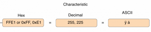
We are accomplishing two things in this method. First, we are getting the character version of the hex values FFE0
6:The firs thing we do is convert the HM-10’s characteristics from FFE1 to character values, 255 and 225.
8:Next, we check to see if we got two characters, and they are 255 and 225
12-23: We do a quick enumeration through the services and characteristics. For each characteristic, for each service, we call the selectedPeripheral setter method. We pass thesetNotifyValue argument totrue. This automatically receives serial data. Each time serial data is received the method
-(void)peripheral:(CBPeripheral*)peripheraldidUpdateValueForCharacteristic:(CBCharacteristic*)characteristicerror:(NSError*)error{//Put RX data collection here.}
We’ll write our RX method when we get to UI, since we’ll set our rxDataLabel to automatically update with incoming data.
Also, the we are setting up an automatic RX notification method. But, another way to do this is by setting thesetNotifyValue to false. Then, each time you want to get RX data you can call thedidUpdateValueForCharacteristic method manually.
-(void)peripheral:(CBPeripheral*)peripheraldidDiscoverDescriptorsForCharacteristic:(CBCharacteristic*)characteristicerror:(NSError*)error{//Store data from the UUID in byte format, save in the bytes variable.constchar*bytes=[(NSData*)[[characteristicUUID]data]bytes];//Check to see if it is two bytes long, and they are both FF and E1.if(bytes&&strlen(bytes)==2&&bytes[0]==(char)255&&bytes[1]==(char)225){// We set the connected peripheral data to the instance peripheral data._selectedPeripheral=peripheral;for(CBService*servicein[_selectedPeripheralservices]){for(CBCharacteristic*characteristicin[servicecharacteristics]){// For every characteristic on every service, on the connected peripheral// set the setNotifyValue to true.[_selectedPeripheralsetNotifyValue:trueforCharacteristic:characteristic];}}}}
**
**
sendValue
This method is called whenever we want to send information to the peripheral. It has data passing argumentstr, but we wont be using it. The app we are writing automatically assemblies a data string and send it to the peripheral each time it is called. To send our data we simply must insure it is in the appropriate variable.
This app takes the values of two slider with a range of -255 to 255. We then do a little data manipulation. On the iOS device a byte takes 8 bits. Same for an unsigned character. But I found if you assign a value greater than 127 then ARC will automatically generate two-bytes for a single unsigned value. To get around this and hang on to full resolution of the Arduino, we convert the slider ranges from 255 to 125-0 or 125-1. The one is a bit set in a switch-array,controlByte. Then, when the Arduino receives the data it converts it back to full range, 255.
Regarding the direction, using the same switch array,controlByte, weset a bit low or high depending on whether the slider indicates 0 to -255 or 0 to 255. Again, when this makes it to the Arduino it is converted into direction of the motors.
Ok! Let’s step through the code.
-(void)sendValue:(NSString*)str{for(CBService*servicein[_selectedPeripheralservices]){for(CBCharacteristic*characteristicin[servicecharacteristics]){// Round the float.steeringValue=lroundf(self.steerSlider.value);accelerationValue=lroundf(self.accelerationSlider.value);// SEND STRING// DIR-MA DIR-MB PWM-MA PWMA-MB EOTC// CON Byte CON Byte 0-255 0-255 :NSMutableData*myData=[NSMutableDatadata];// CONTROL BYTE// BIT: 7=CAN'T BE USED// BIT: 6=// BIT: 5=Breaklights ON// BIT: 4=Headlights ON// BIT: 3=127+ MOTOR B// BIT: 2=127+ MOTOR A// BIT: 1=MOTOR B DIR// BIT: 0=MOTOR A DIRNSUIntegercontrolByte=0;//Steer value is negative number.if(steeringValue<0){// Set the reverse bit.controlByte|=1<<0;steeringValue=(steeringValue*-1);}// Acceleration value is a negative number.if(accelerationValue<0){// Set the reverse bit.controlByte|=1<<1;accelerationValue=(accelerationValue*-1);}// If steer motor is greater than 127.if(steeringValue>127){// Set the bit indicating 128-255.controlByte|=1<<2;// Remove excess from text.labelsteeringValue-=128;}// If steer motor is greater than 127.if(accelerationValue>127){// Set the bit indicating 128-255.controlByte|=1<<3;// Remove excess from text.labelaccelerationValue-=128;}//NSLog(@"After: %i", controlByte);// Breaklights//controlByte |= 1 << 5;// Headlights//controlByte |= 1 << 4;// Load all the data into myData.[myDataappendBytes:&controlBytelength:sizeof(unsignedchar)];[myDataappendBytes:&steeringValuelength:sizeof(unsignedchar)];[myDataappendBytes:&accelerationValuelength:sizeof(unsignedchar)];// Create a string with all the data, formatted in ASCII.NSString*strData=[[NSStringalloc]initWithData:myDataencoding:NSASCIIStringEncoding];// Add the end-of-transmission character to allow the// Arduino to parse the stringstr=[NSStringstringWithFormat:@"%@:",strData];// Write the str variable with all our movement data.[_selectedPeripheralwriteValue:[strdataUsingEncoding:NSUTF8StringEncoding]forCharacteristic:characteristictype:CBCharacteristicWriteWithoutResponse];self.rxData=@" ";}}}
3-6:Like before, we are enumerating through all services and characteristics on our connected peripheral.
8-9: We get the slider values, round them into an integer and load them into appropriate integer variables steeringValue and accelerationValue.
14:Setup a data variable to hold our send string.
25:We create a byte variable to act as our switch-array.
29-42:Determine direction the motors should go based on the sign of the sliders.
45-58: Decide whether we need to divide the range.
67-69:Load the processed data into data variable.
72: Create a string using the data we’ve processed, then, convert it to ASCII to be sent to the Arduino.
75:Add the “:” character, which will act as our end-of-transmission character.
78:Finally, we send the completed data string to the peripheral.
Voila!
Full source code for this projects can be found here:
This is a short note on how to setup a C programming environment for the FTDI chip in bit banging mode, since that’s what I had difficulty doing.
There may be easier ways to go about this, but I wanted to use GCC to compile a small C program to control the 8 IOs. The purpose was to write a small command-line program that would reset my LPC1114 before and after programming.
You must have both the ftd2xx.h and ftd2xx.lib in the same directory as you attempt to build.
6. I then wrote two programs, one to send DTR and CTS high and low in order to reset the LPC1114 into programming mode. ** Second, to send DTR and CTS high and low in order to send the LPC1114 into **run program mode. The idea being, I could use the typical Sparkfun FTDI programmer to program my LPC1114.
 Setting Up the GCC Compiler**
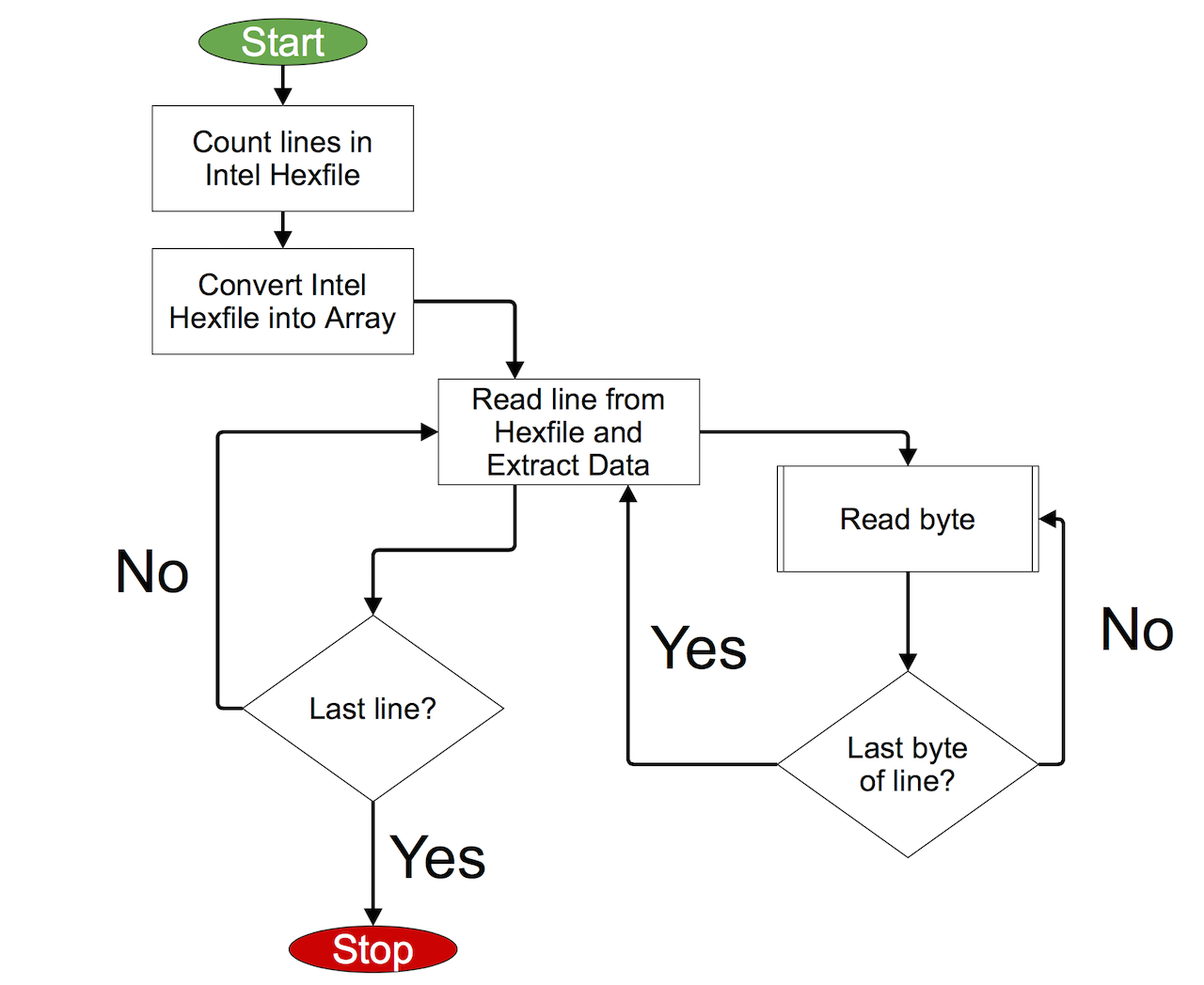

 I love the Arduino Pro Mini (APM) for robot building. It is small, powerful, robust, it’s just good stuff all around. When I decided to build an LPC board I wanted it to copy it in design.
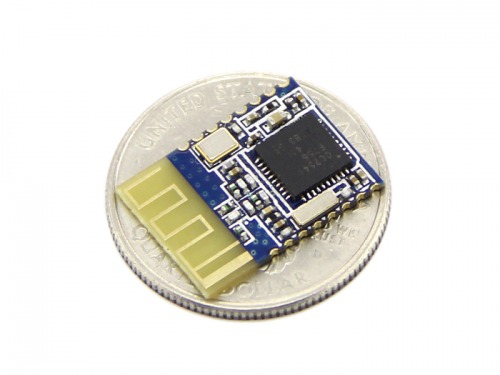


 **
**