Originally posted on www.letsmakerobots.com
I thought I should give my Kossel a "Robot" page, since Silas asked what the Kossel was, and I told him, "A 3D Printer," to which my precocious son replied, "No, it's a robot."
A lot of the information here is a copy from my build blog, but I've re-thought it's presentation slightly, since there preexist two build guides for the Kossel.
Both are put together by organizations selling Kossel kits. Blokmer's guide is much more detailed and slow paced. Of course, I purchased my kit from builda3dprinter (here on referred to as B3DP) and tried to use their guide as much is possible, that said, the B3DP guide has a lot missing information. I wont bitch too much, since I've enjoyed their kit, but it does bring me to how I'll approach the information here.
I'm going to write this guide as a supplement to existing build guides. For example, the Kossel has an auto-level probe that is somewhat problematic to assemble. Both guides did a poor job of explaining several key parts of its assembly. Therefore, I'll focus primarily on missing information.
Purchasing the Kossel materials:

I sourced a few parts from China and purchased the major parts from www.builda3dprinter.eu .
eBay and Fasttech
3 x NEMA 17 Motors : $42.00
1 x Planetary Stepper : $60.00
12V, 30A Power Supply : $31.39
Ramps and A4988 Drivers : $31.00
Arduino Mega : $15.81
J-head MK-V, 0.4MM Nozzle, 1.75MM : $36.99

For the rest, I bought several "kits" from www.builda3dprinter.eu.
B3DP Kits
Kossel Kit (plastic parts) : $55
Nuts and Bolts kit for Kossel : $30
OpenBeam Kit for Kossel : $70
Rails to Wheels conversion kit : $50
The rest : $115
Shipping: ~$50.00
Total for Essentials: $587.19

After purchasing all the essentials I bought a few things I felt would make the build neat.
Scrunchy Wire Wrap : $10.02
Little zip-ties x 100: $3.85
Big zip-ties x 50: $4.85
Colorful heat-shrink x 140: $11.78
Total for Neatness: $30.50
Total Essetials and Neatness: $617.69

Regarding www.builda3dprinter.eu
I need to say I've mixed feelings towards B3DP. Being a mental-health worker, when someone has mixed feelings we create a T-Chart of pros and cons. Here's mine on B3DP kit.
Cons:
- Shorted ~20 M3 Nuts.
- Six weeks for processing and delivery
- No clear documentation on the effector provided
- Missing Allen key, springs, and safety pin (for auto-probe). This is not included in their list of what's not included .
- Pin connectors are cheap and not reliable
- Huge holes in documentation (Blokmer rocks this one).
Pros:
- Plastic part quality is excellent.
- Responded to delays by giving me a free borisillicate plate .
- Communicate well (they responded quickly to all my questions).
- Their kits do work well together.
In fairness, I'm not done with the build, but writing this out, I'd say I would buy B3DP kits again .
The bit it's difficult to put a price on is part precision and synergize. Since the parts are meant to work together, calibration is much simplier (still not easy). For instance, instead of having to measure out the length of rods, carriage offset, etc. B3DP provided a Marlin (firmware for delta) with these measurements already input. In sum, half of the calibration is already done by B3DP.

Purchase "Doh"s!
1. Effector mismatch:
B3DP provided me with a MK V end effector and I bought MK IV J-Head extruder that was advertised as an MK V. Point to you eBay. So far, this hasn't caused any problems, I simply pulled the brass end off my extruder and pushed it into place. Not sure of the open area between the effector plastic and the PTFE tubing will cause me problems down the road, like filament bunching.

2. Must have a Geared Stepper motor for extruder:
I purchased my stepper motors in a lot of five. I thought, "I'll use 3 for the X, Y, Z axes and one 1 for the extruder." Well, this is where I should have done more research. The original design for the Kossel requires a NEMA 17 Geared Stepper Motor. So, I broke down and ordered a geared stepper-motor for the extruder. I was a little under budget and felt it was a better choice rather than struggling trying to get the current motor I had to work with what B3DP sent.
But to be clear the extruder from B3DP is built for a stepper-motor with a 8mm shaft. Actually, the parts are from the original design which called for a geared-stepper motor and a spur-gear with 22 teeth, with a 8mm diameter shaft. The "common" NEMA17 has a 5mm diameter shaft. I've seen a few extruder designs that use a regular stepper and a 5mm diamter spur-gear, but that is not what comes with the B3DP kit.
Assembly
Like I stated, I'm no going into a lot of detail about the assembly, since there exist two guides. But I'll include time-lapse of most of the build (what was easy to film) and notes on stuff not in the exist build-guides.
The Blokemer guide states I should tap and drill the Traxxas ends and the carbon rods. I bought a metric tap and die set from Harbor Freight, but when I examined the pieces I received from B3DP I noticed the headless bolts were too small to catch the inside of the carbon rods. Also, I wasn't sure how to use my tap and die; this devolved into the realization I had the wrong thread sizes. Makes sense, I was using a US tool and parts from everywhere else but the US.
Well, I lucked out. According to the B3DP manual you don't need to tap anything. Just screw the headless bolts into the Traxxas ends, then use slow-setting Epoxy to glue the ends into the carbon rods. Screwing the headless bolts in the Traxxas ends went great. Um, gluing was another matter.
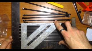
Not much to say about setting up the jigs for the carbon rods and Traxxas ends. Just follow the instructions on pages 3-6 of the Blomker guide . I used a square and a speed-square, the square to align the rails flush, then the speed-square to align the machine screws at one end. I've read that the arms can deviate from the 180mm outlined by the guide, but they should all be the same length. My goal was to identify rods longer than the others and file them down a little.
Post-build note: I found to "spare" objects in my plastic parts that came from B3DP--I realized they are jig bits . Doh.
2. Gluing Traxxas Ends (and a big F'up)
I bought some cheap slow setting epoxy from Harbor Freight. I mixed it with a chop-stick (a favorite tool) and began to apply it to the Traxxas ends. Then, I f'ed up.
I dropped one of the Traxxas ends into the epoxy. I tried cleaning it in alcohol and acetone. But there was still some residue that prevented the ball-joint from moving as freely as I wanted. Sigh. I went ahead and ordered more Traxxas heads, so, if anyone needs an extra because they dropped it in epoxy, just let me know. I'll have eleven.
One more note, be sure to wipe excess epoxy from the Traxxas end and rod joint. I was worried about an improper seal between the two and left the globulated extra. It leaked into the crevices of the 1515 Beam . Of course, I thought, "I'll just make sure to turn the yucky part inside when I put the pieces together so it's not noticeable." Well, the nuts bolting it to the plastic pieces are also on the inside. In short, it caused a lot of problems. I'd wipe them off before setting them in place on the jigs if I could do it over.
I didn't like the name "Bottom Assembly" so, I renamed this step: Bottom Triforce assembly. For the most part, smooth sailing. Just make sure you barely screw the nuts on. If they are too tight you can't get the plastic lips to close around them. Also, they have a top and bottom.
Adding the shafts to the bottom Triforce was a little tricky. First, it should be noted, there is an "up" and a "down" to the Triforce pieces:


The little circular tabs on the bottom Triforce assembly are for printing purposes and may be removed with a sharp knife and steady hand. In the absence of a steady hand, a lot of blood and an emergency-room visit will suffice.
Also, don't screw any bolts down too tight until you press all pieces together. I had reviewed the section in the Blokmer guide, pages 28-32, but I realized the need for give from all sides was greater than expected. You'll notice towards the end of my video I was struggling not to look like a complete idiot trying to push all the pieces together.

Of course, I didn't realize this until I already had bolted the bottom Triforce down and started trying to shove the first shaft in place. I quickly pulled the bottom apart, flipped the odd piece I had so all my plastic pieces had the two-prong guide at the "top."
Now, I've seen half-dozen different ways to press the 1515 into printed plastic. I tried my heat gun, but was really wary I'd deform a piece and I would have to wait 6 weeks to get another from B3DP. I ended up using the following tools:
To press the rods in, I started the rod into the first nut. Then, when it started to get tight, I put a little bike oil (the green bottle) around the edges, flipped over the assembly, and put it in my lap. I pressed the end of the rod I had started against the tile floor and beat on the receiving end (assembly) with a balled fist.

Well, this worked great. A little too great. The rod slipped past being flush. This is where the screwdriver and hammer came in. I simply left the assembly in my lap, but raised the rod off the floor. Then with the tip of the screwdriver against the end of the 1515 rod, I tapped against the screwdriver with the hammer. This allowed me to align the 1515 rod flush with the bottom plastic of the Triforce assembly.
Carriages assembly went pretty well. I had to tap the holes for most of the bolts on the carriages, since there was printer-webs still in the holes. But after the holes were clear it was pretty straight forward. I followed the guide from B3DP .
A few notes: If you haven't sorted your bolts, might be a good idea to do it now. If all your bolts are lumped together digital-calipers are a godsend. You just measure from directly under the head, to the end of the shaft.

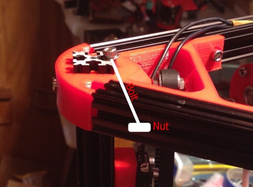
There are three nuts that will need to be pressed into the plastic of the carriage assembly. I used a heat gut to soften the plastic of the intended holes, then pressed the nut slightly in place by placing the tip of a flat-head screwdriver over the nut and tapping it with a hammer. This method worked well. One exception, there are three nuts, but two of the bolts are 25mm and one is 16mm. The 16mm bolt is not long enough to catch the threads of the nut unless you tap it deep into its hole. I hope this picture makes it clear:
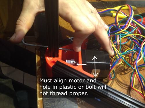
Bottom endstops and motors went smooth.
Only bits of advice on the motors are: Make sure you tap the holes in the plastic to prevent any plastic shards from misaligning your bolt as you try to screw it into the motor hole.
Also, don't tighten any bolts down until all your bolts are started correctly . I found they often were misthreading, which I attributed to such a harsh angle.
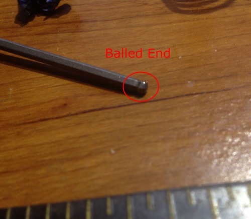
Oh, one more bit, purchase a long 2mm Balled Allen Key for this process. As you may notice at the beginning of my video I tried with a short, balless Allen key to no avail.
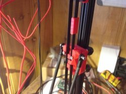
6. Carriage Arms and Effector Assembly
A couple notes,
The carriage assembly is pretty straight forward, just make sure you follow the instructions and don't get in a hurry. But the effector I had a little difficulty putting together. Mainly, the round part of the J-head wouldn't fit into the hole. I've tried to avoid using a heatgun as much as possible, but here I used it to warm the plastic enough and pressed the J-head into place.
Here I become a little peeved at B3DP. First, there are three parts they do not include in " The Rest " kit, but also don't mention in the " What's not included " section. They are the spring, safety pin, and Allen-key for the auto-level .
The auto-level bit is a little tricky to put together. You will need to source three parts: The safety pin, Allen-key, and springs. I ordered an Allen-key off eBay. The safety pin I "borrowed" from my wife's things. And the springs I pulled from some old pins. After much fiddling I was able to piece something together.
Now, I need to state, in my original blog I was a little unfair to B3DP. I bitched about them sending a button-switch for the auto-probe. The problem was they provided a button switch instead of an button and arm switch.
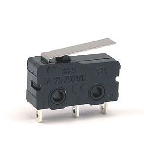
Arm and Button

Button Switch

This should not have bothered me too much, since the three end-stops worked. But when it came to the auto-level, the Allen-key crook was supposed to catch the metal arm of the above shown switches, guiding it down to the button. Well, I found when the Allen-key came to sit on the button, instead of pressing it down it would slide either to the left or right. And it didn't seem to matter how much tweaking I did, I couldn't get it to sit right. In the end, I bought the "appropriate" switch at Radio Shack for $3.
Here is what my auto-level looked like after tweaking. When I tested it unmounted it worked.

But, when I mounted the auto-probe and started using it, I found the arm would catch underneath the safety-pin bolt. Hmm.
Therefore, I feel I owe B3DP half an apology.
I ended up using the switch I was sent, effectively, and I apologize for bitching about the wrong switch. But , to get the switch I was sent to work properly, I had to layer heatshrink, over, and over. This builds the arm up to the point it can't help but catch the button. And the heatshrink has some natural resistance to it. This necessary modification probably needs to make it into the B3DP guide.
Regarding the power-supply.

I tried buying a cheap computer-power cord from eBay. But after I sliced the end off and found less copper than in telephone wire. I sacrificed one of my old computer power cords. The powercord wasn't as long as I'd like, but it had enough copper to pull the possible 30A the PSU could source.
To wire the PSU,
- Green <---> Ground
- White <---> N(eutral)
- Black <---> L(ive)
Also, if you are using that fasttech.com PSU, I noticed it came to me with the 240v as default. If you're in the states make sure you flip the switch on the side.
After wiring my PSU to the Ramps I turned it on and looked for blue-smoke. Nothing. Waahoo!
But I had another problem. The Mega underneath wasn't getting power. Well, I scratched my head for a bit and then actually read the Ramps manual. Apparently the diode that had been taped to the underbelly of my Ramps is what enabled it to be powered from a 12V PSU. I soldered it in place.
After soldering the diode everything appeared to be working. I continued to wire everything else up like proper.
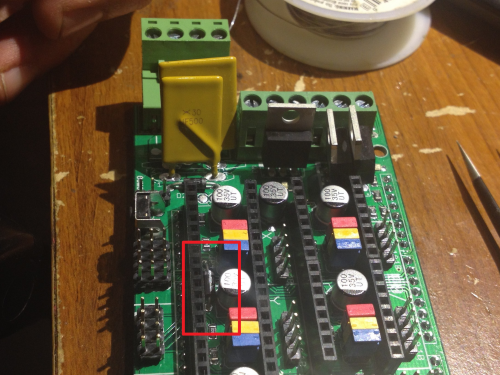
12V to Arduino Mega Diode placement
Here, I switched gears and put the top Triforce together.
One note I'll make. Again, the top Triforce has a "bottom" and a "top." It has to do with the tensioner bolt, it must angle from the top-outside to the bottom-inside. Like this,
After, I got a hankering to actually put the top on and the belts in place. It took a little courage, since B3DP sent my timing belts in one role. I had to make cuts and was worried they had given me just enough belt and if I made a cut that was a little off would have to wait on another belt. But it was in vain, I had enough.

To cut the belts I just strung them up as shown and left about four rubber-teeth past the end of the linker groove. The little extra room can be adjusted when the top Triforce is put on. There are three tension bolts for this purpose.
This is what the belt should look like in place, except the should go below the carriage or it will knock into the end-stops before carriage.
(Sidenote, from here on I'm using a lot of pictures, since the Kossel is a little difficult to video given its physical size)
I then tightened the top Triforce and quickly hooked up the Ramps. I uploaded the Marlin firmware and was able to get the motors to respond to one direction. The problem came when I tried to hook the cooling fan to the Ramps. Two of the three FETs were putting out 0Vs. Waaa-waaah.
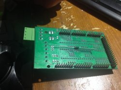
Apparently, the power control FETs on the Ramps were bad ?

I found out later (Brassfly and Bdk6 actually figured it out) that it was not bad FETs. It was a trace-short somewhere on the first 12V power rail. Oh well. I ordered another Ramps board for $14 and took a break from the build for 18 days while it found its way to me.
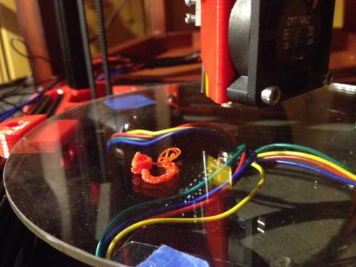
8. It's Alive!
The evening I received the new Ramps board I wired everything up. Sure enough, I powered the thing on and all the blue-fairies stayined in their Silicon homes. I then ran the Blink sketch to check the power FETs on pins 8, 9, 10. They all powered on like expected, spitting out 12Vs.
Next, I uploaded Blokmer's Marlin sketch. Big mistake.
Blokmer and B3DP both provide a Marlin sketch with "typical" measurements already plugged into the Configuration.cpp. I didn't know this. I had essentially put diesel into a gasoline engine.
- Blokmer's Marlin Firmware Specific to Blokmer's Kossel, Pronterface, and Slicer (.zip; for Windows)
- B3DP's Setup Page . It links to Marlin Firmware specific to B3DP Kossel, Pronterface, and KISSlice.
Of course, I pulled a lot of my hair out using Blokmer's firmware with a B3DP build. In the end, I downloaded B3DP's Marlin and Blokmer's zip file. That is, I used the appropriate Marlin with Pronterface and Slicer.
Before I move on though, I'd like to go over wiring.
Here is the B3DP wiring chart:

Of course, my stepper-motors had different color wires, but I guessed and got it right. Really, I figure they would either move up or down, then I could switch them if needed. A word of caution, make sure you wire each stepper to its corresponding end-stop. If not, when you home the end-stops for the first time one or two of the motors will stop, but the other two or one will continue because their end stop hasn't been triggered, resulting in your belt(s) coming loose. E.g., motor X will hit end-stop Z, but not turn off because the X end-stop hasn't been switched. And the X end-stop wont switch off because motor Z has stopped because its end-stop has be triggered.
Clear as mud? Just make sure each end-stop is wired to the appropriate motor.
Regarding the thermistor, it is non-polarized. Just plug it in.
Ok. I'm going to consider the "Mechanical" section of this build complete. Now, I'll begin working on the hard stuff: Calibration .