
This article is part of a series.
- Part 1 - Metallurgy 101 - AVR Lesson Journal
- Part 2 - This Article
- Part 3 - Metallurgy 101 - AVR UART
Originally posted on www.letsmakerobots.com
This is a continuation of my Robot Metallurgy 101 Lesson Journal.
After I was able to get my motors moving using the SN754410 I became a little obessessed with understanding AVR PWM architecture. There are several tutorials that helped me a lot:
- Newbie Hack’s “Intro to PWM.”
- Newbie Hack’s “Control a Servo with PWM.”
- humanHardDrive’s “PWM”
- maxEmbedded’s “AVR Timers – PWM MODE”
In the end, I ripped maxEmbedded code and got my PB3 LED working in about 10 minutes. Then, I spent the next three evenings reading trying to figure out what maxEmbedded’s code was doing.
Really, it was the register and bit names that were tripping me up. Each had names like, “TCCROA1” and “OCR0A”, and so forth. Each is an initialism. This was a problem for me, I was soon lost in a jungle of intialisms, which represented abstract concepts, such as other intialisms. I felt as if I were bumbling through a George MacDonald dissertation on an orc language:
NOTE: Dear reader, I apologize if that video confused you more. Again, this is a journal so to help me remember what I learn. And I find adding a story to ridicules abstractions is necessary for me.
Alright, now that I had a little story in my head to handle the intialisms learning PWM on the AVR flowed a little easier.
Here is my reference list:
1. TCCR = Timer/Counter Control Register.
On the ATtiny1634 there are 4 control registers. One is 8-bit and the other is 16-bit. Though, this journal will stick with the Arduino standard, meaning, I’ll use my 16-bit as an 8-bit. Here are the four Timer/Counter Control Register names:
- TCCROA (8-bit)
- TCCROB (8-bit)
- TCCR1A (16-bit)
- TCCR1B (16-bit)
TCCROA (8-bit timer) and TCCROB (16-bit timer) control the PWM functions of pins.
- TCCROA/B control pins PA5 and PA6.
- TCCR1A/B control pins PC0 and PB3.
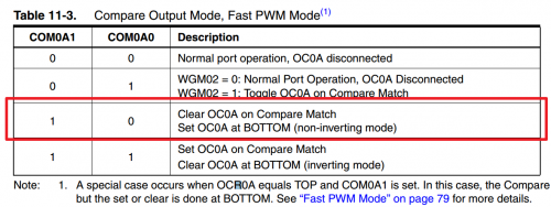
2. COM = Compare Output Mode
There are four bits per TCCR register that control the compare output of each pin. This is where the magic happens. If a pin is setup in compare output mode, it will only go high when the counter is equal to or higher than a number you provide. For instance,
- Is timer greater than 100? Then go high.
This is the essence of PWM. You provide a number, in our case a number between 0-255 since it is an 8-bit counter, and if the timer is equal to or greater than your number, the pin will be HIGH. Then, the timer will continue to count up and will reset to 0 after 255 is reached. Mind you, the comparison is made every tick of the counter, so when it resets to 0 the comparison will be made and the pin will go LOW ago. Voila!
There are four COM bits in each TCCR register, two control the output of one pin.
Found in TCCR0A:
- COM0A0 and COM0A0 control pin PC0.
- COM0B0 and COM0B0 control pin PA5.
Found in TCCR1A:
- COM1A0 and COM1A1 control pin PB3.
- COM1B0 and COM1B1 control pin PA6.
Now, switching these bits can create many different types of output. But I stuck with Arduino standard.
3. WGM = Wave Form Generation (for 8-bit)
There are 3 bits that control the type of PWM we end up with. There are all sorts of wave-forms, but the main three are:
- Phase Correct
- CTC
- Fast PWM
(Here is an Arduino article that explains them a bit.)
The one I’ll invoke is Fast PWM,
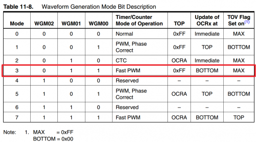
We select this by setting WGM00 and WGM01 bits.
4. How to set the TCCR registers.
So, setting things up, the code will look something like this,
// Demonstration of PWM on an ATtiny1634.
// C. Thomas Brittain

#define F_CPU 8000000    // AVR clock frequency in Hz, used by util/delay.h
#include <avr/io.h>
#include <util/delay.h>

//Initialize PWM
void pwm_init()
{
	//This is the first PWM register, TCNT0.  It is 8 bit.  Both PIN PA5 and PA6 are set to clear on compare,
	//then set at bottom; this makes them non-inverting.  The WGM bits are set to for "Fast PWM MODE"
	//and this clears at the top, "0x00FF."
	TCCR0A = 0b10100011; // WORKS FOR OC0A, OC0B
	TCCR0B = 0b00000001; // WORKS FOR OC0A, OC0B

	//This is the second PWM register;TCNT1.  It is 8 bit.  Both PIN PB3 and PC0 are set to clear on compare,
	//then set at bottom; this makes them non-inverting.  The WGM bits are set to for "Fast PWM MODE"
	//and this clears at the top, "0x00FF."
	TCCR1A = 0b10100001;  //WORKS FOR OC1A, OC1B
	TCCR1B = 0b00001001;  //WORKS FOR OC1A, OC1B

	//This sets the PWM pins as outputs.
	DDRB |= (1<<PINB3);
	DDRA |= (1<<PINA5);
	DDRA |= (1<<PINA6);
	DDRC |= (1<<PINC0);

}
I left the assignment of the TCCR registers in a binary format. This was just easier for me, but you could as easily use bitwise operations, e.g.,
TCCR1A |= (1<<COM1A1)|(1<<WGM01)
You notice we set the COM0A1 or COM1A1 bits, but later I’ll change this so they are not set at initialization. I found if you connect the pins to the timers at the beginning, then they’ll constantly have a nominal voltage on them. This is made clearer if you have an LED on the pin. Therefore, unless you set the COM0A1 and COM1A1 bits low then the LED will never fully turn off.
Also, we have to set the data direction registers for the PWM pins to outputs.
Now, that the initialization is done, let’s look at the code I used to demonstrate PWM on the ATtiny1634.
int main()
{
	uint8_t brightness;

	// initialize timer0 in PWM mode
	pwm_init();

	//Setup several duty-cycle counters to show differential PWM channels.
	uint8_t brightness2 = 0;
	uint8_t brightness3 = 0;
	uint8_t brightness4 = 0;

	//Let's only do this 3 times before turning PWM off.
	for (int counterB = 0; counterB < 2; ++counterB){

		//The main duty PWM cycle counter will also be our loop counter. (0-255)
		for (brightness = 255; brightness > 0; --brightness)
			{
				// set the brightness as duty cycle
				brightness2 = brightness2 + 1;
				brightness3 = brightness3 + 2;
				brightness4 = brightness4 + 10;

				OCR0A = brightness;   // PCO0
				OCR0B = brightness2;  // PA5
				OCR1A = brightness3;  // PB3
				OCR1B = brightness4;  // PA6

				//Delay to make changes visible.
				_delay_ms(40);
			}

			//After 3 loops clear the PWM channels by setting COM0A1 and COM0B1 bits low.
			//If this is not done then there will be a nominal voltage on these pins due to
			//the internal pull-ups setting them as outputs.
			TCCR0A = 0b00000011; // WORKS FOR OC0A, OC0B
			TCCR1A = 0b00000011; // WORKS FOR OC0A, OC0B
		}
}
You’ll notice this is a modified “Fade” sketch from the Arduino world.
The above code provided this output,
How the magic happens in AVR is around the output comparison registers,
- OCR0A – controls PC0
- OCR0B – controls PA5
- OCR1A – controls PB3
- OCR1B – controls PA6
Basically, the OCR registers flip the pin HIGH or LOW (as setup by the TCCR) based upon the number you assign to it. If you assign OCR0A a value you of 144, it’ll be LOW (0v) for 144 clock cycles (TCNT) and HIGH (5v) for 111 clock cycles. This gives us our PWM. Booyah!
- OCROA = 127;
This sets PC0 to approximately 2.5v. (127/255bit * 5v = ~2.5v)
- OCR1A = 255;
This sets PB3 to 5v. (255/255bit * 5v = 5v)
Ok, here’s the tricky one,
- OCR0A = 0;
This should set PC0 to 0v, but that’s not the case. When we set the COM registers (COM0A1, etc.) there are internal pull-up resistors connected to the corsponding pin. This results in a constant nominal voltage unless the COM register is set low again.
This can be done using the XOR operator on the TCCR register,
- TCCRO ^= (1«COM0A0)
This should set the PC0 pin to 0v.
It’s really that simple…well, unless you want to mess with the type of PWM you are creating. Ugh.
5. ATtiny1634 analogWrite.h
After I figured out how to use PWM on the ATtiny1634, I started thinking how nice it would be to re-create the Arduino library for it.
Being able to write,
- analogWrite(pin, strength)
had a lot of appeal to me.
I played with it a bit and ended up with the following,
#ifndef analogWrite1634
#define analogWrite1634

#include <avr/io.h>
#include <util/delay.h>

void analogWrite(int PWM_PinSelect, int duty);

// initialize PWM
void pwm_init()
{
	//Define PWM pins.
	#define PWM_PC0 1
	#define PWM_PA5 2
	#define PWM_PA6 3
	#define PWM_PB3 4

	//This is the first PWM register, TCNT0.  It is 8 bit.  Both PIN PA5 and PA6 are set to clear on compare,
	//then set at bottom; this makes them non-inverting.  The WGM bits are set to for "Fast PWM MODE"
	//and this clears at the top, "0x00FF."
	TCCR0A = 0b00000011; // WORKS FOR OC0A, OC0B
	TCCR0B = 0b00000001; // WORKS FOR OC0A, OC0B

	//This is the second PWM register;TCNT1.  It is 8 bit.  Both PIN PB3 and PC0 are set to clear on compare,
	//then set at bottom; this makes them non-inverting.  The WGM bits are set to for "Fast PWM MODE"
	//and this clears at the top, "0x00FF."
	TCCR1A = 0b00000001;  //WORKS FOR OC1A, OC1B
	TCCR1B = 0b00001001;  //WORKS FOR OC1A, OC1B

	//This sets the PWM pins as outputs.
	DDRB |= (1<<PINB3);
	DDRA |= (1<<PINA5);
	DDRA |= (1<<PINA6);
	DDRC |= (1<<PINC0);

}

void analogWrite(int PWM_PinSelect, int duty){

	//Make sure we were passed a number in-range.
	if (duty > 255) duty = 255;
	if (duty < 1) duty = 0;

	//Sets PWM for PC0
	if (PWM_PinSelect == 1){
		if (duty > 0){
			TCCR0A |= (1<<COM0A1);
			OCR0A = duty;
		}
		else {
			TCCR0A ^= (1<<COM0A1);
		}
	}

	//Sets PWM for PA5
	if (PWM_PinSelect == 2){
		if (duty > 0){
			TCCR0A |= (1<<COM0B1);
			OCR0B = duty;
		}
		else {
			TCCR0A ^= (1<<COM0B1);
		}
	}

	//Sets PWM for PA6
	if (PWM_PinSelect == 3){
		if (duty > 0){
			TCCR1A |= (1<<COM1B1);
			OCR1B = duty;
		}
		else {
			TCCR1A ^= (1<<COM1B1);
		}
	}

	//Sets PWM for PB3
	if (PWM_PinSelect == 4){
		if (duty > 0){
			TCCR1A |= (1<<COM1A1);
			OCR1A = duty;
		}
		else {
			TCCR1A	 ^= (1<<COM1A1);
		}
	}

}

#endif
A synopsis of the library,
- Lines 1-2 and 90 make sure the library is only included once.
- Lines 13-16 define the ATtiny1634 pins.
- 18-28 setup the TCCR registers (notice, the pins start out off to prevent nominal voltage).
- 41-42 makes sure our PWM value is in range.
- 46-85 control the PWM on each pin, with an else statement to gives us a true zero voltage in the case a PWM value of 0 is passed to the function.
I saved this as 1634analogWrite.h and then wrote a sketch to use
// program to change brightness of an LED
// demonstration of PWM
//void Tiny1634_PWM(int PWM_PinSelect, int duty);

#define F_CPU 8000000    // AVR clock frequency in Hz, used by util/delay.h
#include <avr/io.h>
#include <util/delay.h>
#include "1634analogWrite.h"

int main()
{
	uint8_t brightness;

	// initialize timer0 in PWM mode
	pwm_init();
	int brightness2 = 255;
	int brightness3 = 255;
	int brightness4 = 255;
	// run forever
	while(1)
	{
		for (brightness = 255; brightness > -1; --brightness)
		{
			analogWrite(PWM_PC0, brightness);
			analogWrite(PWM_PB3, brightness2);
			analogWrite(PWM_PA5, brightness3);
			analogWrite(PWM_PA6, brightness4);

			_delay_ms(10);
			brightness2 = brightness2 - 5;
			brightness3 = brightness3 - 10;
			brightness4 = brightness4 - 15;

			if (brightness == 0)
			{
				_delay_ms(1000);
			}
			if(brightness2 < 0) brightness2 =255;
			if(brightness3 < 0) brightness3 =255;
			if(brightness4 < 0) brightness4 =255;
		}

	}
}
Ok. I’ll revisit this probably with a complete H-Bridge control library.
As always, please feel free to correct my f’ups. :)