
Originally posted on www.letsmakerobots.com
Here are some random notes on working with the HM-10.
- Working RX/TX LEDs
- How upgrade the HM-10
- Pseudo Star-Networking HM-10s
Working RX/TX LEDs
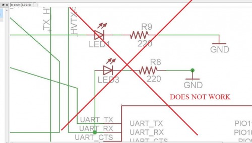
I spent some time trying to find a way to create RX/TX traffic LEDs for the HM-10 breakout. This might be easy for some, but it was a real thinker for me. The HM-10 is TTL, which as it was explained me, means that the line is high while idling and low to represent data. The problem here is the typical LED setup doesn't work. Sadly, this is the setup I used in two of my fabricated boards.
Well, this stupid mistake has been staring me in the face. Especially since a few guys ordered my board and mentioned politely, "It only flashes when large amounts of data go through."
After asking around I was told the best way to approach this problem was to use a PNP transistor. The guys at LMR pretty much gave me the solution here . The people here are brilliant. (Please don't tell them I'm not, I want to hang with the cool-kids for a bit before they find out my mom still dresses me.)
But while LMR was helping me I found Sparkfun's solution to the problem on one of their Xbee Explorer boards . In essence, the LEDs are wired from in between 3.3v and the TX/RX lines, this allows them to act as sinks whenever the data is coming through. As long as the LED is a green, blue or other with a 3.1v drop, then the voltage being sunk doesn't interfere with the data.
Of course, this is risky. The CC2540 is a nifty chip, but it isn't meant to be a high-current uC. I dug through the datasheet to see what the current sink rating of the RX/TX pins (2 & 3) were. Well...it's not in the datasheet! But then I came across this post .
So, I checked chapter 7.3 of the CC2540 User Guide .
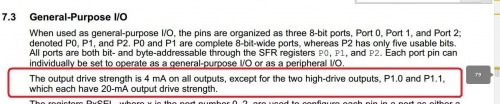
Well, there we go. So, I breadboarded a circuit and found it worked. But I was only brave enough to use a 1k resistor.
Eventually Brassfly helped me work through the math,
"Given that the voltage drop across the forward biased junction of a red LED is about 2 Vdc (we will call that Vf) the total current through the LED/Resistor is equal to Vsupply-Vf/R, or in this case 3.3V-2V/1000=.0013A=1.3mA....If they are bright enough then don’t worry about it. If not, you might then consider using a 470 ohm resistor (2.7mA) or even 330 ohm resistor (3.9mA)."
So, I made up a fresh version of the HM-10 breakout board (v.9.9) with this LED setup. I wired it up. And, it seems to be working.

Again, can't use yellow or red LEDs on the RX/TX lines, since they do not create a high-enough voltage drop to signal the CC2540 low).
How upgrade the HM-10
(NOTE: You can only upgrade versions 507 or later, according to Jnhuamoa)
1. Visit the HM-10
website
and learn
all
about the HM-10 upgrade process.

2. Download the lastest firmware version file. (Make sure your HM-10 is a CC2540, if it's CC2541 use that file).

3. Before we proceed, here's my bitchy disclaimer. Re-read the instructions and b_ eware all ye who try to upload firmware and don't blame me for problems, like the death of your HM-10 :P _
4. Open Realterm (or your preferred serial terminal).
5. Wire your HM-10's serial connection as described in my earlier post .
6. You are about to cross the point of no return. Open a serial connection to the HM-10 and if you are prepared for the worst, type: "AT+SBLUP" and the module should reply, "SBLUP+OK." Congratulations, you've bricked your HM-10--well, at least until the upgrade process is complete.
7. Now, CLOSE YOUR SERIAL CONNECTION in Realterm. Yes, I forgot to close the connection myself and was pissed because I thought I had bricked my HM-10 when I tried the next step. I'm a hack, hacking with a hacksaw.
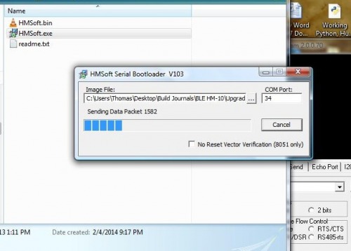
8. Unzip the "HMSoft-10-2540-V522.zip" (or the latest version, respectively) into a folder. There should be several files in the folder, open HMSoft.exe
9. Now,
click on the ellipsis and select "HMSoft.bin"
file. Then, type the number of your com port. You don't need to include anything but the number (e.g., COM34 becomes 34).
10. Pray (for the HM-10 this works best if to Nyarlathotep ).
11. Click "Load Image." The upload process should start pretty quick and should take approximately a minute and a half to complete.
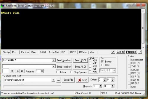
Do not remove power or screw with the wiring until you see the following:

12. Click "Ok" and open Realterm. Bring up a serial connection and type: "AT+VERS?" It should respond, "HMSoft v521." That's not a typo, even though we uploaded the V522 version it responds saying it is V521? You got me. But it works ok :)
Pseudo Star-Networking HM-10s
Setup up at least three units.
Unit #1 ("Master")
- AT+ROLE2
- AT+IMME1
- AT+CONxxxSLAVE#1xxxx
Unit #2 (Slave #A)
- AT+ADDR? Write the address down. Mine replied, "OK+ADDR:883314DD8015"
- AT+MODE1
Unit #3 (Slave #B)
-
AT+ADDR? Write the address down.Mine replied, "OK+ADDR:883314DD8016"
-
AT+MODE1
Oh, one more bit. You need to wire pin 4 on the Arduino to the HM-10 Master's reset line. Since there really isn't anyway to reset the slave and the master at the same time. This gets us around the timeout for both, slave and master.
- RESET<----1k Resistor----->D4 on Arduino
Then use the following code, changing your addresses respectively.
// Crap code for HM-10 pseudo-Networking
// By the crappy code Thomas Brittain, aka, Ladvien.

String inputString = "";         // a string to hold incoming data
boolean stringComplete = false;  // whether the string is completeString inputString = "";         // a string to hold incoming data

float time;
float oldTime;

void setup() {
// initialize serial:
Serial.begin(9600);
pinMode(4, OUTPUT);
digitalWrite(4, LOW);
}

void HM10Reset(){
  Serial.print("AT+RESET");
  delay(220);
  digitalWrite(4, HIGH);
  delay(100);
  digitalWrite(4, LOW);
  delay(150);
}

void loop() {
  // print the string when a newline arrives:
  Serial.write("AT+CON883314DD8016");
  delay(150);
  Serial.print("From first node!  Seconds ago last here: ");
  time = millis();
  Serial.println((time-oldTime)/1000);
  oldTime = millis();
  delay(250);
  HM10Reset();
  Serial.write("AT+CON883314DD8015");
  delay(150);
  Serial.println("From second node!");
  delay(150);
  HM10Reset();
}

void serialEvent() {
  while (Serial.available()) {
  // get the new byte:
  char inChar = (char)Serial.read();
  // add it to the inputString:
  delay(50);
  inputString += inChar;
  stringComplete = true;
}

}
Not going to lie. I'm pretty dissapointed with how complicated the firmware makes it to switch between nodes. Although, I've only begun to play with firmware versions greater than V303.
I couldn't do much better than about 2.84 seconds switching between nodes. This simply wont do for me. And, of course, this rate goes up with more nodes. So, a swarm of little robots controlled this way would be unmanagable.
I tried tweaking the timing of everything in the code. The HM-10 wasn't having it. If I lowered the delay following an AT command it, the command wouldn't take. This would often cause the nodes to become stuck (waiting for timeout, still connected, etc.) Also, the hardware reset on the HM-10 is said to be 100ms, but I'm finding it unhappy with much less than 250ms.
Anyway, if anyone else wants to carry the banner my suggestion is uping the buad rate and sticking with hardware resets, like in my ATtiny Bitsy Spider board.