I’ve waited to finish incorporating my Raspberry Pi into my bot for an ample bit. But since I know so little about electricity, I swore to myself I wouldn’t add my Pi to my bot until I was absolutely sure I wouldn’t fry it.
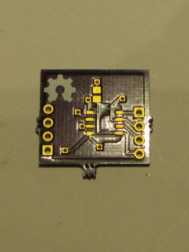
Well, I’m still not “absolutely” sure, but I feel this little optoisolator has brought me a lot closer. This builds on my post a week or so ago about making Eagle parts.
I plan to actually list out what tweaks a Wheezy image needs to get this optoisolator build to work. It’s actually pretty easy–but whatever you, don’t be lured in by quick2wire. Those buggers wasted most of my day :(
If anyone has questions let me know.
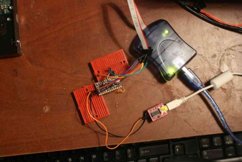
Oh, one note. When I populated the board I used 4.7k resistors on the Arduino side, but I pulled off everything on the Raspberry Pi side. It seems the Pi has built in pull-ups that do the job rather well.
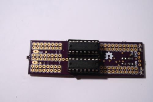
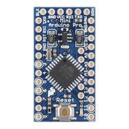
I decided to try making an Arduino Pro Mini at home. Being done, it’s not worth it. You can buy one for a dollar more than you can make them, and it took awhile to populate. Although, it’s “fun.”
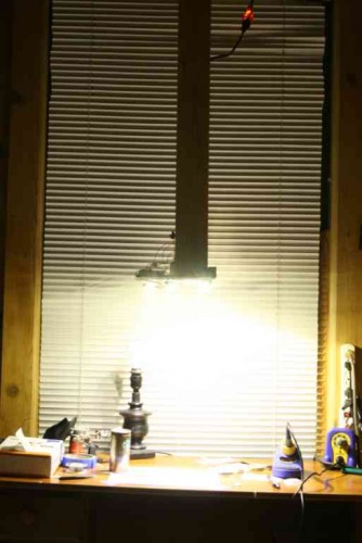
This projects was also a chance for me to test the Spying-Stalactite I built.
I’ve enjoyed it. It allows me to reflect on my strategy while populating boards. It’s simply a drop down with some high-powered LEDs (~2500 lumen), heatsink, and coolant fan. It has a hole for my iphone to do the recording. Cheap and simple. Although, I need to diffuse the light, as you might see by the video that it washes out the details of the projects. Also, I’ll add a few more lights and do away with the tungsten lamp, since the iphone is constantly in a white-balance battle as I move infront of the mixed lightsources.
I populated this board; everything came out fine (although, it was much more difficult trying not to block the camera with my head). I popped it into Atmel studio and it read out the device voltage and signature. Of course, I bricked it, as I seem to do a lot.
My next projects is a Fuse Doctor. :)
I had ordered the boards from OSHPark and had planned on making three. So, I populated another and took some time programming it. I’ve outlined my steps below:
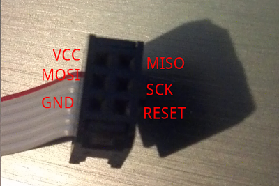
1. Hook up the AVRISP MKII
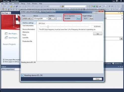
2. Open Atmel Studio. Go to Tools – Device Programming.
3. Setup:
Tool: AVRISP mkII
Device: ATmega328P
Interface: ISP
Click apply
4. Read Target voltage (it should be ~5V). Read Device Signature.
**
**
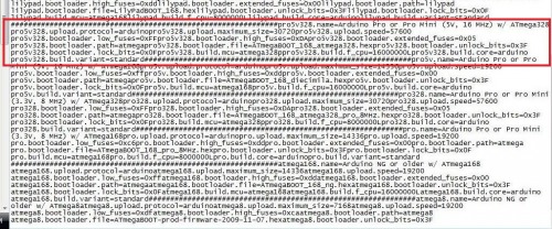
Open boards.txt that comes with Arduino (\Desktop\arduino-1.0.3\hardware\arduino\boards.txt).
Scroll down to the area marked:
8. Pull the programming information for the board from this area. Now, I’ve bricked a few boards, but I think I’ve figured this one out. When programming this board with the MKII and Atmel Studio, you should follow this order.
1. Set the fuses:
Extended: 0xFD
High: 0xDA
Low: 0xFF
(Double check the board file to make sure I didn’t make typos)
Hit “Program”
2. Upload Bootloader.
“The bootloader for the 5v, 16mhz Arduino Pro Mini (which is what I built) is “ATmegaBOOT_168_atmega328.hex (Desktop\arduino-1.0.3\hardware\arduino\bootloaders\atmega\ATmegaBOOT_168_atmega328.hex). It’s important to note that the 3.3v and 5v versions use different bootloaders.
Go to the Memories tab
Hit the browse ellipsis.
Select the “ATmegaBOOT_168_atmega328.hex”
(Double check the boards file to make sure I’m not screwing you up).
Hit program.
3 Set Lock Bits.
Go to the “Lock bits” tab.
Check the boards.txt file for Lockbit number
Lockbit: 0xCF
(Double check the boards.txt. I don’t take blame for bricked boards :P).
Hit “Program”
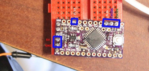
9 Upload the Blink Sketch; the LED by the reset button should blink.
10 Let me know how it went. If you bricked a chip using these instructions, let me know so I can modify them quick.
Now that I’m used to the camera and stalactite, I plan to annotate my next board for tips on working with 0402s.
Hope all are well.
ps. Birdmun et al., sorry bout the copyright issues. Not a professional at anything, especially video editing :)
Addendum:Please don’t watch my videos. After Birdmun’s comment I found Hack-a-Day has created better videos (shakes fist at Hack-a-Day) and I don’t want anyone to waste anyone’s time. Although, mine has a better soundtrack and less mutton-chops :)
Original: I was speaking with TeleFox and Birdmun about finding an optoisolator for use with my Raspberry Pi; I had gotten some samples of these ICs: ADUM1250ARZ. Well, for awhile now I’ve wanted to share my dumb-luck methods for designing a board around a sampled IC.
I finally got in my Mega Mini Motor (M3) shield that I designed. I was surprised, after populating the board: It actually worked. The board came about after making the Arduino Mega Mini. I noticed I wouldn’t really be reducing the bulk of my bot because of the amount of wiring it would take to get logic to the Arduino Motor Driver shield I was using. Therefore, I set out to design a motor driver shield that would plug right into the MegaMini. I broke out Eagle and some datasheets on an assortment of ICs.
I started out working with the L298D chip, but quickly got frustrated with the way it set on the MegaMini footprint. Plus, the flyback diodes were pissing me off. I had remembered reading that the SN754410 had internal ESD diodes. I started playing with the chip layout and got a board design I was pretty happy with.
I’ll attempt a full write up later;I’m pretty mentally fatigued from learning html/css (I know, easy. But as many know by now, cognitively, I’m as slow as a snail on salt.)
 **
**