Beaglebone Black

8/25/13:

This fellow here has made some pretty nifty walkthroughs on the rtl8192 and the Chronodot (DS3231) RTC on the Arch Linux. Though I’ve not attempted his instructions (been burnt out on this board) I believe his instructions will get a reliable WiFi connection with the rtl8192, using Arch Linux, on the B^3.

Also, when I get the energy, the pinout at the bottom of this page has a mistake or two. As Zaius pointed out.

EDIT: Ok. Don’t use the pinout until I research more. I’m getting conflicting information on what pins are what in Mode 7. The reference manual is stating one thing, but other sources are agreeing with me. I’m guessing Zaius is dead on; version issues. When I’ve got it sorted I’ll update.

7/3/13:

Not much yet, still working on stable wifi. I thought I might as well share my work log; embarrassing as it may be.

If there are some Linux wise in the crowd (especially those knowing Arch Linux) would you mind taking a look at my work flow? I’ve got the wifi module working, though, it’s not as stable as I’d like.

http://cthomasbrittain.wordpress.com/2013/07/03/installing-8192cu-module-on-the-b3-running-arch-linux/

6/22/13

Wow. Sorry all, been more than a month since I updated this post.

I’ve not given up on the BBB as a robot platform; I realized I didn’t know Linux well enough to begin tweaking it on embedded devices (well, devices lacking community support, at least). I’ve spent the last month reading about Linux and trying to wrap my head around it (that and fixing all of our bust-a-mucated cars).

I grew up Microsoft and over this last month all household computers have switched to dual-booting Ubuntu 12.04 and Microsoft X. And router will soon make the switch to OpenWRT.

Back to the BBB; the Realtek WiFi dongle that drove me mad has been solved by these guys. I’ve not had time to attempt their walkthroughs, but it is on the agenda.

I haven’t found an Arch Linux image file, so I thought I’d cook one and post it for anyone who needs it.

[Arch Linux for the Beaglebone Black – 6-20-13]

If anyone actually downloads the image, will you confirm it works for you?

Off topic a bit, I’m not sure if anyone else uses iDevices; but I did run into this app that I greatly enjoy.

ServerAuditor

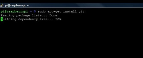
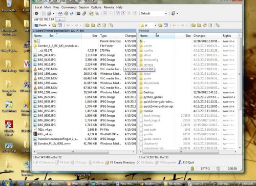
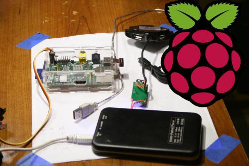
It’ll let you tunnel (SSH) into your Linux devices from either from an iPhone or iPad X. I’ve enjoyed this for two reasons: I can keep an eye on how a program is compiling on the Raspberry Pi while watching a movie with the family, and, I like the feeling of running Linux on a closed system. I understand it’s a falsity, but it’s still comforting.

I hope all are well.

5/20/13

Well, I think I could best describe this point in economic terms. It’s the where I’ve realized my productive efficiency is being restricted due to the current inabilities of technology.

Figure 1

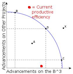
In essence, this graph shows that I cannot reach my desired productive efficiency (getting the B^3 to do the tricks I want it). Really, I’d be happy at point C (even though point D is probably better for me and my family). The problem is technology limitations are restricting me from getting to point C on the curve. And it’s bugging the hell out of me. At first, I thought this was completely due to my ineptitude (which is partially true), but there is another barrier, a seemingly hidden one.

The current Beaglebone driver technology is a hidden barrier to this productivity point.

I’ve read the warnings TinHead gave on treating embedded devices like computers. But if they don’t carry some extrordinary functions then what separates them from really, really fast microcontrollers? No. I’m pushing to have some basic PC functionality.

For instance,

  1. WiFi capability.
  2. Easy access to a graphical interface (note, I’m not stating GUI).
  3. Ability to utilize higher-level programming languages (Python, C++, etc).

Really, that’s it. A few features to allow rapid prototyping while haranessing the power of open software.

To me, if these three features are achieved, then I feel like the device is complete. Though, I should state, I’ve realize these three features are no simple feat.

So, where’s the Beaglebone Black? Not there.

Some things not supported that will need to be for me to get to point C (Fig. 1).

  1. Ability to plug in cheap, low-power WiFi dongles and get them going in under an hour. Let’s be honest. Cheap is what 90% of us will go with. It allows us to do more with our budgets. Therefore, if an embedded device in anyway can utilize cheap peripherals, then let’s focus on making it happen. 1
  2. Better power-management on the software side. Several distros will shutdown the board during boot-up, as the peak above 500mA. The designers suggestion? Don’t plug anything in until the board is up. Sounds ok, right? Well, don’t forget there is no hot-plugging on the USB, microSD, or HDMI. The drivers haven’t been written yet. I’m pretty sure this is due to drivers, since I’ve read through the BBB datasheet and the power supply hardware seems sound.
  3. Ability to adjust the HDMI output. At one point, I had one point, I was trying to get Arch Linux up and I couldn’t get in via SSH. So, I plugged it into the only HDMI monitor I have and tried to adjust the ssh.config file. The problem? I couldn’t see what was commented out due to the overscan. I dig through Google group where the board designers rest; guess what? There is no current way to adjust the video output. 2

Therefore, my conclusion (though, my insanity is rising), is:

Figure 2

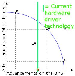
All this to say, my wife has taken away my Beaglebone Black until that green line moves farther out.

Yes, I am little-cat whipped, but she has said, “You’re doing this to relax, not work a second job. I’d rather you work on some other projectss for awhile.” Hey, being married is the only thing keeping me sane. Well, her and you guys (and girls, if Max didn’t run them off :P).

5/16/13:

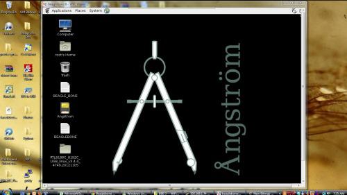
I’ve finally got the Black Bone near where I’ve got my Pi. Here, the old Bone is running an updated Angstrom (4gb) build, using WiFi dongle, and is connected to a 1A wall-wart (connected to microUSB not barrel-jack). When I’m off work today I’ll try to complete a “Box to Wireless” walkthrough for good ‘ole Angstrom.

(Question, anyone else feel like there’s a Mason’s conspiracy going on in the embedded world?)

I think I got near understanding TinHead’s post: Don’t treat an embedded device like a PC? I dunno.

5/15/13

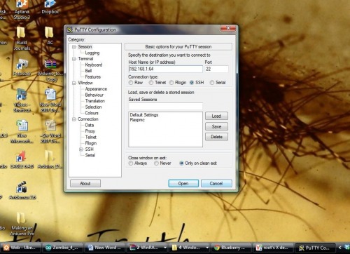
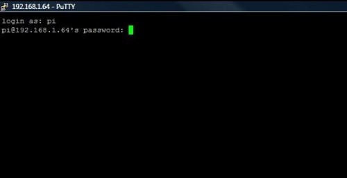
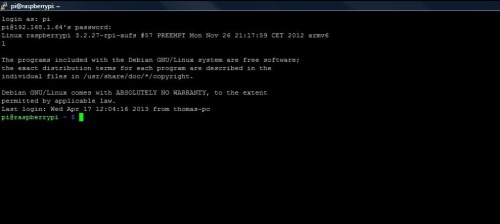
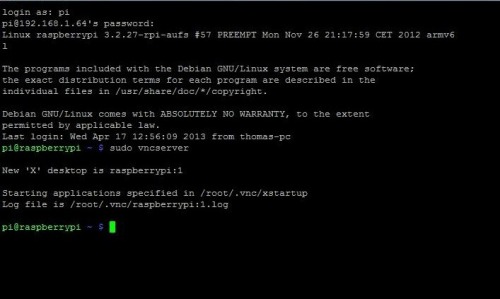
I was able to get my WiFi dongle up by adding the realtek8192 kernel. Not sure all I did, but it works. So, as soon as I can get some repeatable steps, I’ll post a walkthrough of setting the Beaglebone Black up with PuTTY, VNC, and WiFi dongle.

5/14/13:b

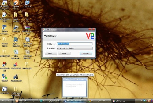
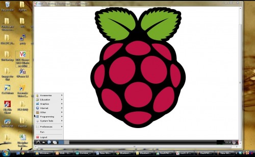
Was able to get RealVNC to pick up Angstrom. Working on getting WiFi dongle up.

5/14/13:a

I added some links to Bonescript GPIO walkthroughs (PWM, Analog, Blinking).

5/12/13:b

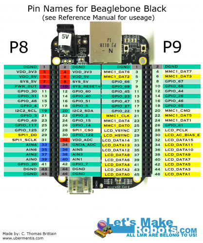
I’ve created a visual guide to mode 7 pinout (added below).

5/12/13:a

I’m pretty frustrated. So, I’m going to back off working on the board until Tuesday when my 8gb microSD comes in. At that point, I’ll use this to reflash my eMMC boot partition and start working two different projectss: Getting Arch Linux going well, and giving in and update && upgrade my Angstrom. Both, I’ll try to write up.

Jerz, or anyone else with a BBB, if you have any notes to add, if you don’t mind shooting me an email I’ll update this post.

Hope everyone had an awesome mother’s day.

5/11/13:c

May I encourage anyone who has yet to order their B^3: Wait.

There are several intense issues being worked out on a hardware-software level. Until then, I feel you’ll be as frustrated as me. Bdk6’s pun says it all: This board is being a bitch.

Some updates:

  • The package manager that came with Angstrom was actually broken for awhile, and no one bothered mentioning it to the community. Instead, there were many posts titled “why won’t opkg work?” Now, I believe it will work if you run update && upgrade, of course, to do that you must have an SD card since it will be larger than 2gb.
  • I got Arch Linux up, briefly (it takes both eMMC and SD).
  • I lost the appropriate boot file for my eMMC. (While attempting Arch Linux).
  • There doesn’t seem to be an easy way to flash eMMC back to stock (I’ve got to wait for a bigger card).
  • One of the only cool things I’ve seen yet is a one wire(ish) pc.
  • The developers are pretty stressed out. I don’t see solid support for a bit. And already seems like a us vs. them between the developers and open community
  • I’m tired. Who’s taking over?

5/11/13:b

So, I attempted getting my WiFi dongle setup (again) using Angstrom’s package manager. I found that everything I tried installing using their package manager would shoot back an error. I read, and I believe the problem is the following must be run to catch the Angstrom stock package manager up with desired packages.

**opkg update ** **opkg upgrade **

I ran them, and guess what? The eMMC does not have enough space to hold the updates. Mother-of-a-Beagle!

Sadly, I’m using a microSD card from an old phone, which is only 2gb. My 8gb is on order.

This, in my opinion, puts the Beaglebone Black on the same level as the Raspberry Pi; that is, it must have a SD card before you can use it (a card larger than 2gb). If someone else finds a way to install things on the B^3 without updating it, let me know, I’ll correct this critique.

5/11/13:a

Wrote up a guide to restore Angstrom to the eMMC.

5/10/13

I screwed up the eMMC partition while trying to get Arch Linux on the Beagle.

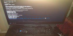
5/9/13: Oh, dear lord. It’s true. Lack of community support kills the Beaglebone.

It took me nearly 9 hours to setup an OS on an MicroSD.

I’ll write it up tomorrow night, after some rest.

Ubuntu on Beaglebone Black:

**

**

5/6/13

I got my Beaglebone Black (BBB, B^3) in today. I thought I’d share my unboxing and general thoughts.

Please don’t take this as Mr. Jones on a Sunday drive, rather, I want to provide the touch-n-feel information for every robot builder here. In short, I don’t want everybody to waste $45 if the BBB is going to turn out to be Beagle sh…, well, you get it.

(Hey, Raspbery Pi puns could fill a library, I can’t make one BBB pun. Shesh.)

BBB Development Group:

https://groups.google.com/forum/?fromgroups=#!categories/beagleboard/beaglebone-black

This is a good place to find info to your specific problem.

Beaglebone Black Educational Material (aka, bathroom reading):

B^3 Manual:

http://circuitco.com/support/index.php?title=BeagleBoneBlack#Hardware_Files

Original Beaglebone tutorials

(these were found by JerZ, thank you sir).

http://www.youtube.com/playlist?list=PLF4A1A7E09E5E260A

Hardware interfacing:

http://www.nathandumont.com/node/250

Robot Support for B^3:

This was found by Vishu,

Robotic Operating Software for BBB

Get Vishu or MaxHirez to explain it; I’m still trying to make a light blink :(

RPi vs BBB discussions:

http://www.element14.com/community/thread/23575?tstart=0

http://www.raspberrypi.org/phpBB3/viewtopic.php?t=41489&p=336995

**Beaglebone Pinout: **

JerZ was trying to explain to me there are several modes for the B^3 pins (he’s run Hello World on it, and I’m sure by this moment he’s run Blink), Regardless, I thought I’d try to whip up a visual for robot building on the B^3.

Keep in mind, these are the pin names – you’ll have to look up on page 69-73 of the reference manual to know how they might be used. Although, almost every pin can be used, regardless of its intended function. Their functions are defined by the software, each pin having 8 modes (0-7).

http://circuitco.com/support/index.php?title=BeagleBoneBlack#Hardware_Files

For example, if your bot is a quadrocopter: You find a real time kernel for Linux and you’d probably set the pins to MODE 7 turning the non-essential pins into GPIO (i.e., sacrificing HDMI, eMMC, etc. lines to GPIO).

JerZ also found this site:

http://blog.pignology.net/2013/05/getting-uart2-devttyo1-working-on.html

Which seems to be an excellent guide on accessing the mux’ed pins (haven’t worked through it yet).

I found this robotics group that put some walkthroughs together on using the GPIOs by way of Bonescript.

  1. Blinking a Led
  2. Analog
  3. PWM

If anyone else following this, please double-check me, I’ll make corrections if needed.

Beaglebone Black and Raspberry Pi:

These are some of the differences I’ve noticed between the Beaglebone Black and the Raspberry Pi.

| | Est. to Upgrade Rpi or BBB | Est. Difficulty to Add | | Real Time Clock | 1 | 0 | | $2.30 | Medium | | Processor Speed | 1GHZ | 700MHZ | | $4.76 | Medium | | Power Switch | 1 | 0 | | $0.83 | Easy | | Reset Switch | 1 | 0 | | $0.83 | Easy | | Boot Switch | 1 | 0 | | $0.83 | Easy | | GPIO | 65 | 26 | | $8.85 | Medium | | Flash Memory | 2GB | 0 | | $5.66 | Easy | | MicroSD (smaller footprint) | 1 | 0 | | $4.35 | Easy | | Serial Ports | 4 | 1 (that’s accessible) | | $1.50 | Hard | | Barrel-jack and MicroUSB power | Yes | No (just microUSB) | | $2.95 | Easy | | Highest Screen Resolution | 1280 x 1024 | 1920 x 1200 | | ~ | ~ | | Peak Power Requirement | 460mA | 475mA | | ~ | ~ | | Supply Current to USB | 500mA | 700mA | | $5.50 | Hard | | USB Host (devices used by BBB or Rpi) | 1 | 2 | | $1.87 | Easy | | USB Client (lets BBB or Rpi be a device) | 1 | 0 | | ~ | ~ | | Plastic Headers for GPIO | 65 | 0 | | $1.95 | Easy | | USB Cable | 1 (Mini USB) | None | | $1.07 | Easy |

The Hardware:

First impressions in a sentence: The hardware looks sound.

Several things make it stand out:

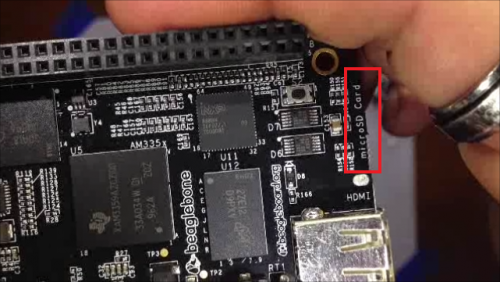
  • It uses a Micro SD card instead of a SD. This allows for a smaller overall size without using an Adafruit Adapter.

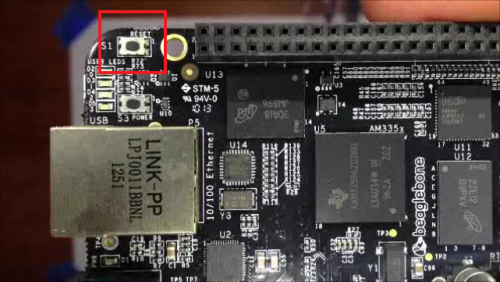
  • It has three tactic switches: (1) power, (2), reset, and (3) a mystery switch. I’m hoping the third is software accessible. The built in powerswitch is a real winner. It means you can tell this guy to keep his £15 and his closed source design.

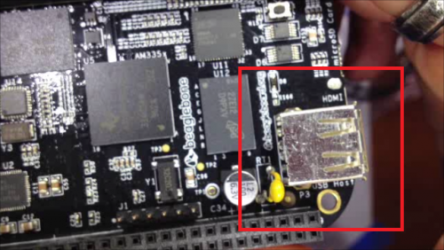
  • It has one USB hub. This is my second greatest concern (after less community support) is having to rely on USB HUBs to connect devices. And, yes, I’m aware an IC, breadboard, and access to hardware IO will allow custom USB deivces. But sometimes don’t you want to just plug-and-go? (Yes, I’m aware I’m lazy.)

  • It has a barrel-jack instead of a Micro USB for power. I don’t know how you feel, but I’d rather have the Micro USB simply because I’ve got a lot of those lying about, whereas barrel-jacks, I’m not sure. Maybe under the decaying skull?

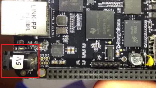
  • It’s open hardware. The RPi claims to be for “educational purposes,” although, it seems the education is restricted to the software. Of course, this is an assumption based on not yet seeing a schematic for the Raspberry Pi silicon bits.

  • It’s TI. They’re nice to me. (I might have a stack of sampled ICs from them…maybe.)

If everyone is alright with me floating this post for a bit, I’m going to try to do a first-boot video tomorrow, then, continue until I’ve built this BBB into a bot.

Hope you’re all well :)

  • Bdk6
  • RPI: 5
  • BBB: 14

  • Maxhirez
  • RPI:1
  • BBB: 2

  • Ladvien:
  • RPI:
  • BBB:1
OpenCV on a Raspberry Pi

Originally posted on www.letsmakerobots.com

Code

No longer afeared of frying my Pi, I’ve moved on to trying to implement some of my bot goals. Like many, I want my bot to be able to interact with people, but I didn’t realize that I’d stumble on this ability.

I’ve looked at many visual processing boards like the CMUcam v4, but I’m not paying $100 for any board. I looked into making one, it looks possible, but not much cheaper. So, I got curious as to what alternatives there are. I stumbled on Hack-a-Day’s recommended article: OpenCV on Raspberry Pi.

Anyway, he provided instructions on setting up OpenCV (open source computer vision) on Raspberry Pi. Of course, it was about 20 minutes later I had the code working on my Pi.

I had been skeptical of the Pi’s ability to run any computer vision software, and morever, it’s usefulness given the Pi’s processing constraints. But once I had it up and running, I noticed it actually ran smoother than I had hoped. Don’t get me wrong, I think it is less than 10FPS, but I could tell it would work for many robot applications More than that, if the Raspberry Pi was used only for the computer vision, then it would still be cheaper than many other hardware driven CV boards.

Basic Raspberry Pi and WiFi Dongle

  • WiFi Dongle: $6.17
  • Raspberry Pi: $35.00
  • SD Card (4g): $2.50
  • Web cam: $8.00
  • Total for Basic RPi: $51.67

Therefore, I went to work on hacking his code.

Many hours later, I ended up with a _very crude _ Raspberry Pi, Ardy, Camera, and Servo orchestration to track my face. Mind you, this is a proof of concept, nothing more at this point. But I hope to eventually have my bot wandering around looking for faces.

Image of Pi VNC. The box outline is being written through i2c.

Pulling apart a little $8 eBay camera.

To Setup the Raspberry Pi:

If you’re setting it up from sratch, start with these instructions.

But if you’re already setup, I think all you need is OpenCV.

$ sudo apt-get install python-opencv

The Code:

The Arduino code reads bytes from the i2c, converts them to characters, then places the characters into an integer array. The Pi is sending 4 numbers, 2 coordinates, x1, y1, x2, y2.

The Python code is “facetracker.py” by Roman Stanchak and James Bowman, I’ve merely added lines 101-105, which load the coordinates of the box around your face into a a string, converts that to a string array. I also added function txrx_i2c(). This function converts the string array into bytes and sends it to the i2c bus.

To change this setup from i2c to UART, focus on the txrx_i2c() in the Python code and the onRead() in the Arduino code. I assure you, UART would be much easier.

If anyone has any questions hollar at me. Oh! And if someone can tell me ways I could optimize this code, I’m all ears

#include <Wire.h>
#define SLAVE_ADDRESS 0x2A
#include <Servo.h>

Servo CamServoX; //Attach the pan servo.
Servo CamServoY; //Attach the tilt servo.

int ServoTimer = 250; // Change to adjust how quickly the servos respond.

int SmallXJump = 3; //Sets the movement amount for small pan jumps
int LargeXJump = 7; //Sets the movement amount for large pan jumps


int SmallYJump = 1; //Sets the movement amount for small pan jumps
int LargeYJump = 2; //Sets the movement amount for large pan jumps

//How close your face is to the edge to trigger a jump.
int SmallYLimit = 40;
int LargeYLimit = 20;

int SmallXLimit = 40;
int LargeXLimit = 20;

//Set servos to initial position.
int posX = 90; //Servo position.
int posY = 90; //Servo position.

int x1; int y1;int x2; int y2; //Holders for frame dimesions.

// Indexes for getting i2c bytes, then, converting them to integers.
int i = 0;
int varI = 0;

//Sets flag to trigger ServoWrite() from the main loop.
//I tried to put this under 'onRequest' call, but the Raspberry Pi kept giving me errors.
//This flagging was a work around.
int NoServoData = 0;

int dim[12]; //Char array for char[] ---> int conversion.
char d[8]; // Char holder array for byte-->char conversion.

void setup() {
    // initialize i2c as slave
    Wire.begin(SLAVE_ADDRESS);
    Wire.onRequest(sendData);
    Wire.onReceive(readData);
    Serial.begin(9600);

    //Attach servos
    CamServoX.attach(10); //Tilt (Y)
    CamServoY.attach(9); //Pan (X)

    //Write initial servo position.
    CamServoX.write(posX);
    CamServoY.write(posY);
}

void loop() {

//Again, this is the work around.  The flag "NoServoData" is set under the i2c onReceive.
if (NoServoData==1){
  ServoWrite();
}

}

//This is just to show the RPi can be written to.  
//Replace with stuff you want to write to the Pi.
char data[] = "Pasta";  
int index = 0;

// callback for sending data
void sendData() {
    Wire.write(data[index]);
    ++index;
    if (index >= 5) {
         index = 0;
    }
 }

// callback for receiving data.
void readData(int numbytes) {

//Holds the chars
int c;

if (Wire.available() > 0){
  while(Wire.available())    // slave may send less than requested
    c = Wire.read();
}
  //Add each integer to a char array.
  //Skip commas ',' and keep adding the integers until char '\0' is received.
  //Then print out the complete string.

  if (c != ','){
    if(c != '\0'){
      d[i] = d[i] + c;  //Appends the characters to an array.
      i++;
    }
  }
  else{
    i=0; //Reset the d char array index.
    if(varI < 7){  //We only want to get integers until we get all four numbers (x1, y1, x2, y2) plus
      dim[varI]=atoi(d); //Convert the d int into ASCII and store it in the dim array.
      d[0]=0;d[1]=0;d[2]=0;d[3]=0;d[4]=0;d[5]=0; //Clear the d array (i2c doesn't like for loops in this function
      varI++; //Increase dim index.
    }
    else{
      //We now have all four numbers, load them into the variables.
      x1=int(dim[4]);
      y1=int(dim[1]);
      x2=int(dim[2]);
      y2=int(dim[3]);

      NoServoData = 1;  //Set the WriteServo() call flag.
      varI=0; //Reset the dim index to prepare for next set of numbers.
      }
   i=0; //Reset some
  }
}

void ServoWrite(){
  int x3 = 160 - x2; // Calculate the distance from the right edge of the screen
  int y3 = 120 - y2; // Calcualte the distance


  //For X Axis
  if(x1 < SmallXLimit ){  //Only do small jumps, since not too far away from the edge.
        if(posX>1){ //If the pan servo is at its edge, do nothing.
          for (int i = 0; i < LargeXJump; i++){
            posX++;  // Set the new position
            CamServoX.write(posX); //Make the adjustment.
            delay(ServoTimer); //Delay between servo increments.
          }
      }
  }

  if(x3 < SmallXLimit){
      if(posX<180){
          for (int i = 0; i < LargeXJump; i++){
            posX--;
            CamServoX.write(posX);
            Serial.println(posX);
            delay(ServoTimer);
          }  
      }
  }


  if(x1 < LargeXLimit){
        if(posX>1){
          for (int i = 0; i < SmallXJump; i++){
            posX++;
            CamServoX.write(posX);
            Serial.println(posX);
            delay(ServoTimer);
          }
      }
  }

  if(x3 < LargeXLimit){
      if(posX<180){
        for (int i = 0; i < SmallXJump; i++){
            posX--;
            CamServoX.write(posX);
            Serial.println(posX);
            delay(ServoTimer);
        }
     }
  }


  //For Y Axis
  if(y1 < SmallYLimit ){
        if(posY>1){
          for (int i = 0; i < SmallYJump; i++){
            posY--;
            CamServoY.write(posY);
            Serial.println(posY);
            delay(ServoTimer);
          }
        }
  }

  if(y3 < SmallYLimit){
      if(posY<180){
        for (int i = 0; i < SmallYJump; i++){
          posY++;
          CamServoY.write(posY);
          Serial.println(posY);
          delay(ServoTimer);
        }
     }
  }


  if(y1 < LargeYLimit){
        if(posY>1){
          for (int i = 0; i < LargeYJump; i++){
            posY--;
            Serial.println(posY);
            CamServoY.write(posY);
            delay(ServoTimer);
          }
      }
  }

  if(y3 < LargeYLimit){
      if(posY<180){
        for (int i = 0; i < LargeYJump; i++){
          posY++;
          CamServoY.write(posY);
          Serial.println(posY);
          delay(ServoTimer);
        }
      }
  }

//Reset servo write flag.
NoServoData=0;
}

Now for the Python Code:

#!/usr/bin/python
"""
Have to execute using "sudo python facedetect.py --cascade=face.xml 0"
(Normal build sudo python "%f")
This program is demonstration for face and object detection using haar-like features.
The program finds faces in a camera image or video stream and displays a red box around them.

Original C implementation by:  ?
Python implementation by: Roman Stanchak, James Bowman
"""
import sys
import cv2.cv as cv
from optparse import OptionParser
import time
import threading
import readline
import pygame
from pygame.locals import *
import sys
import smbus

# Parameters for haar detection
# From the API:
# The default parameters (scale_factor=2, min_neighbors=3, flags=0) are tuned
# for accurate yet slow object detection. For a faster operation on real video
# images the settings are:
# scale_factor=1.2, min_neighbors=2, flags=CV_HAAR_DO_CANNY_PRUNING,
# min_size=<minimum possible face size

min_size = (20, 20)
image_scale = 2
haar_scale = 1.2
min_neighbors = 2
haar_flags = 0

"""i2c Code"""
bus = smbus.SMBus(1) # Open up a i@C bus.
address = 0x2a # Setup Arduino address

sendstring = "" # This will be my send variable (RPI-to-Arduino)
bytearraytowrite = [] #Actual array for holding bytes after conversion from string.

#This function actually does the writing to the I2C bus.
def toWrite(a):
	global sendstring
	global bytearraytowrite
	bytearraytowrite = map(ord, sendstring) #This rewrites the string as bytes.
	for i in a:
		bus.write_byte(address, i)

def txrx_i2c():
	global sendstring
	#while True:
	sdata = ""
	rdata = ""
	for i in range(0, 5):
			rdata += chr(bus.read_byte(address));
	#print rdata
	#print bytearraytowrite
	#print "".join(map(chr, bytearraytowrite)) #Will convert bytearray to string.

	#Writes the key commands to the i2c bus.
	toWrite(bytearraytowrite)


	#time.sleep(.6);

def detect_and_draw(img, cascade):
    global sendstring

    # allocate temporary images
    gray = cv.CreateImage((img.width,img.height), 8, 1)
    small_img = cv.CreateImage((cv.Round(img.width / image_scale),
			       cv.Round (img.height / image_scale)), 8, 1)

    # convert color input image to grayscale
    cv.CvtColor(img, gray, cv.CV_BGR2GRAY)

    # scale input image for faster processing
    cv.Resize(gray, small_img, cv.CV_INTER_LINEAR)

    cv.EqualizeHist(small_img, small_img)

    if(cascade):
        t = cv.GetTickCount()
        faces = cv.HaarDetectObjects(small_img, cascade, cv.CreateMemStorage(0),
                                     haar_scale, min_neighbors, haar_flags, min_size)
        t = cv.GetTickCount() - t
        print "detection time = %gms" % (t/(cv.GetTickFrequency()*1000.))
        if faces:
            for ((x, y, w, h), n) in faces:
                # the input to cv.HaarDetectObjects was resized, so scale the
                # bounding box of each face and convert it to two CvPoints
                pt1 = (int(x * image_scale), int(y * image_scale))
                pt2 = (int((x + w) * image_scale), int((y + h) * image_scale))
                cv.Rectangle(img, pt1, pt2, cv.RGB(255, 0, 0), 3, 8, 0)
                x1 = int(x * image_scale)
                y1 = int(y * image_scale)
                x2 = int((x + w) * image_scale)
                y2 = int((y + h) * image_scale)
                sendstring = str(x1) + "," + str(y1) + "," + str(x2) + "," + str(y2) + ","
                sendstring = sendstring.translate(None, '() ')
                print sendstring
                txrx_i2c()
                sendstring = ""
    cv.ShowImage("result", img)

if __name__ == '__main__':

    parser = OptionParser(usage = "usage: %prog [options] [filename|camera_index]")
    parser.add_option("-c", "--cascade", action="store", dest="cascade", type="str", help="Haar cascade file, default %default", default = "../data/haarcascades/haarcascade_frontalface_alt.xml")
    (options, args) = parser.parse_args()

    cascade = cv.Load(options.cascade)

    if len(args) != 1:
        parser.print_help()
        sys.exit(1)

    input_name = args[0]
    if input_name.isdigit():
        #Where the image is actually captured from camera. "capture" is the variable holding image.
        capture = cv.CreateCameraCapture(int(input_name))
    else:
        capture = None

    cv.NamedWindow("result", 1)

    width = 160 #leave None for auto-detection
    height = 120 #leave None for auto-detection

    if width is None:
    	width = int(cv.GetCaptureProperty(capture, cv.CV_CAP_PROP_FRAME_WIDTH)) #Gets the width of the image.
    else:
    	cv.SetCaptureProperty(capture,cv.CV_CAP_PROP_FRAME_WIDTH,width) #Gets the width of the image.

    if height is None:
	height = int(cv.GetCaptureProperty(capture, cv.CV_CAP_PROP_FRAME_HEIGHT))
    else:
	cv.SetCaptureProperty(capture,cv.CV_CAP_PROP_FRAME_HEIGHT,height)

    if capture: #If "capture" actually got an image.
        frame_copy = None
        while True:

            frame = cv.QueryFrame(capture)
            if not frame:
                cv.WaitKey(0)
                break
            if not frame_copy:
                frame_copy = cv.CreateImage((frame.width,frame.height),
                                            cv.IPL_DEPTH_8U, frame.nChannels)

#                frame_copy = cv.CreateImage((frame.width,frame.height),
#                                            cv.IPL_DEPTH_8U, frame.nChannels)

            if frame.origin == cv.IPL_ORIGIN_TL:
                cv.Copy(frame, frame_copy)
            else:
                cv.Flip(frame, frame_copy, 0)

            detect_and_draw(frame_copy, cascade)

            if cv.WaitKey(10) >= 0:
                break
    else:
        image = cv.LoadImage(input_name, 1)
        detect_and_draw(image, cascade)
        cv.WaitKey(0)

    cv.DestroyWindow("result")
Pi Power -- How I Made a Battery Powered USB Hub

Originally posted on www.letsmakerobots.com

As I prepare to start adding peripherals to my Pi Bot, I wanted to be sure to get around the 700ma power budget the Pi has. After searching for a cheap battery powered USB hub and finding little, I decided to hack up a few cheap(ish) parts and make my own.

  1. USB Hub: $1.39

  2. 5000mAh Battery: $17.93

  3. DC-DC Converter: $2.76

Total: $22.08

The Battery Hack:

1. Crack it open.

**

**

2. Find POWER and GND.

**

**

**

**

3. Wire it up.

**

**

4. Make a small hole for wires and bring wires out.

**

**

5. Solder the respective leads to the DC-DC converter.

**

**

6. Smile, then sit through my way too long of a video to make it into the HUB.

Hope all are well. :)

NOTE: Regarding the error at the end of the video. Don’t panic (that’s what I did). I actually found out this had nothing to do with my hub, it had to do with plugging an iPhone into a Raspberry Pi.

NOTE2: I realize I used the wrong “hearty,” my brain has problems typing homonyms and parahomonyms. :P

Blueberry Pi -- How I Setup My Raspberry Pi as a Robot Base

Originally posted on www.letsmakerobots.com

This article is specific:How I personally would setup my Raspberry Pi to act as robot base. But, I’ll be clear, this is one of nth possible setups. A chessboard has 64 squares but those working the board allow for innumerable possibilities.

That aside, here we go:

1. Get Berryboot. Berryboot will allow you to download several Raspberry Pi images.

Now extract the zip files to a blank SD card.

Put the BerryBoot SD card in your Pi and boot it up.

2. Setup RPi with Raspbian Wheezy (first option).

**

**

3. Setup your WiFi dongle. I believe BerryBoot will now setup your WiFi dongle on initial boot, which it did for me (even gave me the option to download the image via WiFi). But, I had trouble getting my WiFi dongle pulled up after booting Raspbian Wheezy.

If you have difficulty with manual WiFi dongle setup, you might try this video.

Lastly, if you are looking for a WiFi dongle for cheap, with good range, and uses very little mAhs (the Pi can only feed about 700mAhs through the USB port). You might try this one, $6.17.

4. Setup PuTTY on your Desktop Computer. Follow this video.This will allow you to begin SSHing into the Pi. That way you don’t have to look at a little RCA screen like me. For those who aren’t familiar with SSH (like I was before this video), the video will explain it. At risk of oversimplification,it allows you to access your Raspberry Pi command line through your desktop.

You have to plug in your Pi’s network number.You can find this by pulling up your wireless hub’s configuration page. You should see what address your Pi is listed at. For some strange reason, if it doesn’t list the device name, just view the page while the Pi is up, then unplug your Pi and refresh the wireless hub configuration page. The device that disappeared is your Pi. I’ve never had to change the port number, but beware you might need to depending on your setup.**

If you want to know whether your have the correct information, try login’ in and if you get a screen like this, your good.

Your username and password are by default:pi, raspberry

Remember! In the case of a Raspberry Pi, always share your password, ‘cause everyone has it anyway :)

Once you have PuTTY setup, you should be able to bring up your Pi command line, something like this:

5. Setup VNCServer on your Raspberry Pi. Follow this video. (Or this walkthrough). Putty will let you access your Pi’s command line, but setting up a VNC will actually allow you to access your Pi’s Desktop GUI from your PC, in the same manner as Putty.

**6. Setup a VNC Client on your Desktop Computer. Real VNC. **There are many different programs, I happened to end up using Real VNC.

Once you have VNC setup on both machines, PuTTY into your Pi and start the VNC server.

$sudo vncserver

Two notes here, if you did better with the video instructions than I did, your vncserver will start automatically on boot. Unfortunately, I have to type it each time (I’m too lazy to figure out the boot part of it). As a result, you’ll have problems running certain Python scripts through VNC if you don’t use $sudo vncserver

You’ll enter your Pi address, but port should be 1 (if I remember the video instructions correctly).

You should end up with at a windowed version of your Raspberry Pi desktop. One more note, somewhere in the video it gets you to setup the “geometry” of the VNC desktop. The limitations you put there will be reflected in the quality of the desktop you see in the window. In essence, if you put in 640x480, that’s the resolution this desktop will end up. So, please, take advantage of the Pi’s GPU :)

Use something like this, “-geometry 1024x728 -depth 24”

7. Resize your SD card to use all its space. (Note, this should already be done by BerryBoot. But other diskimages will limit your SD card to 2GB, regardless of its actual size).

8. Git manager will allow you to pull code from git hubs (again, this should already be installed, but just in case).

I**nstall the git manager: **

At Raspberry Pi prompt: **$sudo apt-get install git**

The way to use it is like so,

At Raspberry Pi prompt: **$sudo git clone https://github.com/adafruit/Adafruit-Raspberry-Pi-Python-Code.git**

9. **Install SMBus. **This is specifically for my setup, since I’ll be using the I2C bus to communicate between the Pi and the Arduino.

At Raspberry Pi prompt: **$sudo apt-get install python-smbus**

10. Any other Python modules you might fancy.

Useful for keystroke, GUI, and other interfacing needs:

Pygame (should come with Raspbian). (sudo apt-get install pygame)

Lady Ada’s Python codes for an array of I2C sensors:

Adafruit I2C library (git)

Access your Raspberry Pi from iDevice web based GUI:

PiUi (git)

Control serial devices:

pySerial (sudo apt-get install python3-pyserial)

(I’ll add other resources as fellow LMRs leave them in the comments).

11. (optional) Install Arduino IDE on Raspberry Pi. This will allow you to program the Arduino directly from your Pi–and if you follow my design, you’ll be able to do so without ever leaving your desktop computer. You can do this by opening the VNC Server, opening the Arduino IDE on the remote desktop, selecting the sketch you want to upload, and as long as your Arduino is connecting by way of USB, you can then upload your sketch from where you sit. This allows for quick changes to Arduino code without switching wires around. Also, I think Kariloy is looking for a way to upload sketches by way of GPIO pins. This would make a cleaner design.

**12. Install WinSCP. This will allow you to transfer files between your desktop and the Pi. **I find this helps with programming management. I’m a messy filer. If I file at all.

13. Take a deep breath.

14. Follow these instructions for making my I2C optoisolator board.

Again, there are many commercial boards that will serve the same function. Also, you can do the same with a USB cable, serial pins to GPIO, or RF connection–basically any way that lets the Arduino and Pi talk at a reasonable speed. The speed restraint will of course depend on your need. I doubt many methods will be apt for running a responsive quadrocopter. But in my case, my Pi is the central nervous system and the Arduino is the autonomous nervous system. The Pi will send directives, but it’s up to the Arduino to manifest them through responsive actuators. And I chose this optoisolator because I didn’t want an voltage restraint on my actuators or fear of frying my Pi.

Once you have the board setup, you can run:

$sudo i2cdetect -y -a 1

This should bring up a list of active I2C registers. You should find your Arduino at whatever address you set in your Arduino code.

Now, I’ve read this fellow’s article on how Raspberry Pi I2C pins are actually 5v tolerant. (Note, this is only for I2C pins, due to their pull-up resistors.)

So in theory, you can skip the optoisolator all together. But that’s you, I’ll stick with my optoisolation.

15. Download my code–or someone cooler’s.

Note, my code is really just the base for a robot. Right now, my it is nothing more than a very, very complex radio controller for a RC car. But someday, I’ll make a real robot :)

**16. Tweak and gut the code as you see fit. **

17. Ask questions: Pretty much everyone on this site is smarter than me, they’ll know the answer.

To other LMRians. Please feel free to tell me how to change, add, or retract from this article. As tired as I am right now, I plan to revise when I’m less muddled.