Try to learn Python while the mail peoples do their magics.
**
**
Flip-off your Python code and get the mail.
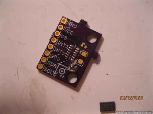
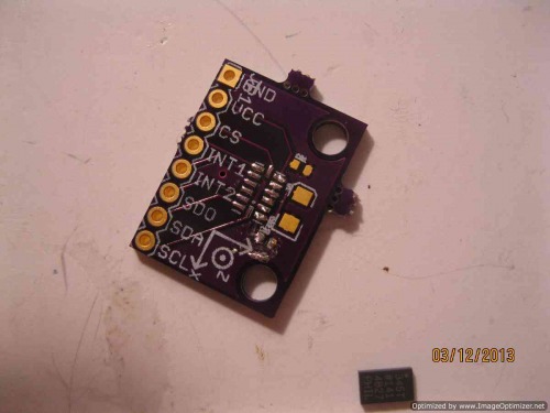
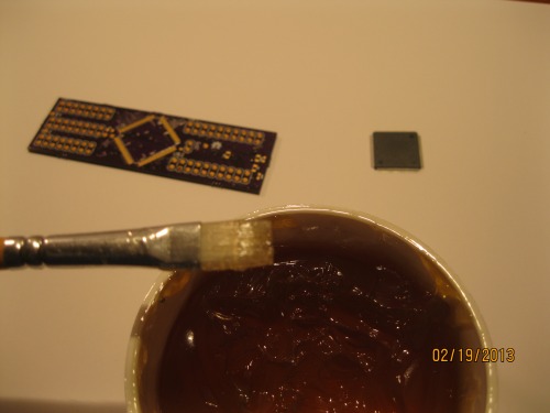
Take everything out. ADXL breakout board, ADXL345 chip, and caps.
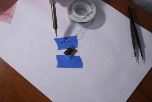
Populate your board. At this point, a good iron will do you well. But as a general rule, start with the largest chip when soldering SMDs. In our case, it is the ADXL345. Paint some solder flux all over the exposed pads. Now, take a very fine solder, such as .022 and put some on the tip of your iron. Drag the droplet of solder across the exposed pads of where the ADXL will go. Now, after the beads have cooled, paint your solder flux over the hardened beads. The idea is to have the chip floating on this flux.
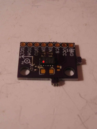
Place the ADXL345 on the invisible flux, hovering over the pads. Make sure the small white dot on the the corner of the chip is in the same place the red is below.
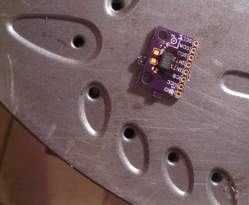
Put the board on an over turned iron. **This is the most important part: **Watch the chip. What you are hoping to see is the chip magically float in place as the solder flux flows out from under the chip, leading to the solder beads bonding with the exposed copper of the ADXL345. **Seriously, don’t look away :). **If for some reason you don’t feel the chip has bonded at each pad, then very lightly press down in the middle of the chip. I said lightly!
**
**
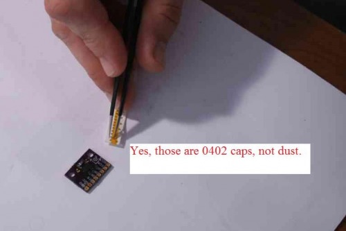
12. Cap that B. Erm, populate the capacitors.
**
**
**
**
13. Plug and pray.
14. Realize it doesn’t work because you suck at life.
15. Pull the ADXL back off, clean the pads with solder wick, and try again.
**
**
16. Repeat step 11, but this time, watch the chip, no seriously.
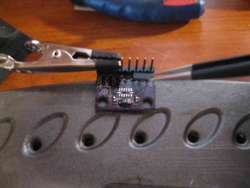
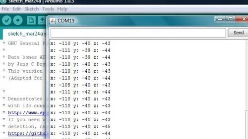
**17. Hook it up and check it out. **The chip is both SPI/I2C ready, but I prefer I2C. So, hook that sucker up to the Arduino and see if it works. This fellow provided code and instructions on connecting are in the code’s comments at the top.
18. Watch as your one dollar(ish) ADXL345 does witchery.
**
**
19. Ponder the ethics of sampling chips, borrowing board layouts from SparkFun, and buying underpriced capacitors from China; all leading to saving you around $12~25–or have a beer.
20. Try not to abuse the sampling previlige.
If you have any questions, I’ll do my ignorant best.
Six months ago I bought my first Arduino. Bought it at the Shack. I’d never worked with electronics, but I had to replace a momentary switch on my computer and wanted more. I quickly woke to the Open Hardware community.
A month later, I was reading about making your own PCBs at home. I made my first home board a few days later. It was a motor driver board, and well, it was a mixed success. Definitely not a looker (http://wp.me/p37cuD-3q). But I was hooked. I wanted to do something more sophisticated. And I was spurred on by a story I once heard about Hunter S. Thompson. It was said that he’d often copy pages out of the Great Gastby because he, “wanted to feel for the music of such great words.” That’s a paraphrase but only cause I didn’t want to reread the forward of Fear and Loathing on the Campaign Trail ‘72 (_once was enough, thanks)._ Still, the logic seemed sound. So, I thought of how to apply it to electronics.
Later, I came across Lady Ada’s article on requesting samples from chip makers and I quickly ordered a dozen ICs; I had no clue about any of them–but their names sounded cool. Two weeks later, I had all sorts of random chips sitting around. I thought on what to do with them; when I came across one of the chips I had ordered: Atmega 2560-16UA. It was a nice little TFQP-100 pin chip, um, the size of a quarter. My mind was reeling. “This was the heart of the biggest bad ass Arduino.”
I quickly pulled up Arduino.cc to download Eagle’s PCB layout for the Arduino Mega. This is where I hit my first snag–um, all that copper board, etchant, and components. Even though I had the main chip it was going to cost a lot to finish Arduino Mega board. And that was if I could. I’d never actually etched a two-sided circuit board. Up to now, I’d only etched one sided and not very well.
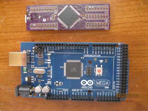
So, I continued to dig for other layouts of the Atmega 2560-16UA that could be used as a Arduino board. That is when I came across this design genuis:
http://jkdevices.com/arduino-megamini
I quickly noticed he provided his design as Open Hardware. To me, this board was magic. It is 3” by 1” and acts exactly like the Arduino Mega. So, I decided, hell or Andy Dick, I was making this board.
Little did I know, there was no Andy Dick, but the other was definitely ahead of me.
1. The Board
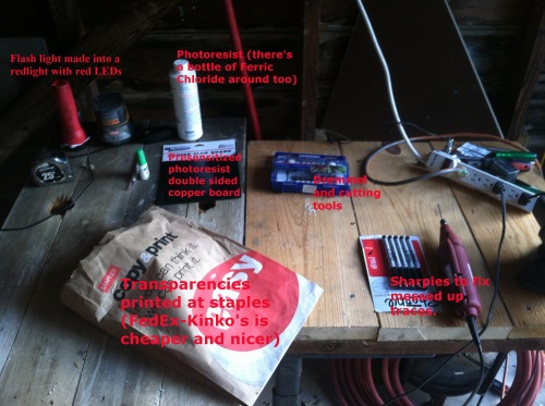
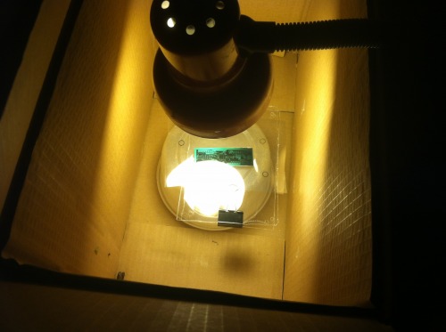
I began Goog-searching any information I could find on etching homemade boards (I’ll provide my fairly comprehensive link list at bottom). After trying all the different methods, I landed on the fact that the lithography method combined with MG Chemicals was probably going to be my best bet. I began collecting everything I needed.
This isn’t going to be a guide on homemade PCBs for three reasons: (1) I don’t ever want to talk about it, (2) others have already done a much better job than I could, (3) there is a better and cheaper way. Stick with me, there is an exciting cost analysis coming.
Cost of materials to attempt etching a Mega Mini:
Presensitized 2-sided Copper Board: $.99
Ferric Chloride: $.99
Positive Developer: $.20
Transparencies: $.46
Total per attempt at etching a Mega Mini: $2.65
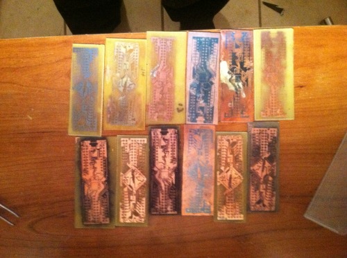
I came to these numbers after 16 attempts. I priced my materials across America, included shipping, cut many boards, and then averaged the costs to come to that final figure. Per attempt, $2.65 was the best I could manage. My problem was several fold. First, I didn’t know what I was doing. I understand this will happen: prototyping is more expensive than production units. Second, I picked a mother-of-some-puppies kinda board to etch. The traces are most commonly 8mil, so, it took me about 14 attempts to get to the point where I knew how to etch such small traces. But attempts 15 and 16 revealed to me a hurdle I simply couldn’t overcome. I had been relying on FedEx-Kinkos and Staples to print my transparencies and I discovered their print size was off.
I had learned that you can compensate for this in Eagle by changing the “Scale” of your print size, sadly, it only lets you change units to the hundredths place. Any thousandths it will round down. My MegaMini PCB needed to be around 1.025. Of course, this would be rounded to 1.02. Suck
Not going to lie. I got depressed. I had sunk much time, money, and passion into etching.
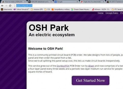
I put the projects on the shelf for awhile. I started working on my bot some. Then, while I was looking at all the neat little things others made on LMR, I noticed in a remark about OSHPark. A while back, I had briefly considered BatchPCB but after I learned the price and tried getting Eagle to produce Gerber files without errors, I gave up. But, I was bored and thought I’d look at OSHPark. I was pretty happy to see I could upload Eagle files directly. Once I got the board uploaded I got depressed again, it was going to be $10.80–oh, wait, that was for three boards. Well, that came to be $3.60 a board. Now, that wasn’t so bad. So I sent off for a trio.
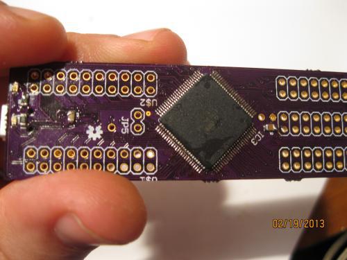
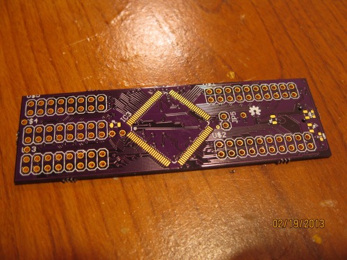
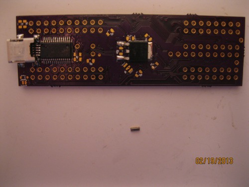
Two weeks later–these amazing little purple boards came in.
Costs for OSHPark Board: $3.60
Several things jumped right out at me
The boards already had their vias in place (and this board has around 60+ micro vias).
It was already lacquered.
The holes were already drilled.
I started thinking about the trade offs between etching my own and boards or sending them off to OSHPark. I decided the only thing I lost was being off the grid. I was originally in love with the idea of something completely made at home. Yet it occurred to me, even if I etched my boards at home I was still buying ICs. Putting me on the grid. So, there wasn’t really anything lost.
Of course, there was also the time trade. I’d gotten my time etching a board down to around an hour. Yet, this didn’t include drilling holes, lacquer, adding vias, etc. Also, there was a lesson of virtue creeping over me: Electronics takes perseverance and patience. Also, I’d been noticing that my best ideas were coming while I was waiting for parts. My mind would run through what I had done, then what I could do different. Thefore, the waiting 15 days for a board didn’t bother me. I didn’t perceive it as time wasted.
As for the price trade off. I only calculated directly used materials for etching boards at home. I didn’t include broken bits, markers used, tap, super-glue, etc. I also hadn’t included capital needed for home production. Drill bits, drill press, lamps, CFL bulbs, etc. Drilling alone was a big under taking for etching boards at home. I’d already sunk $30 into a used drill press (good price and I’ve used it for many other things). But the small bits needed were expensive and broke easy. I will say, I learned to break fewer bits by making sure I taped my board down to a block of wood. It was when the board angled and put the bit in a bind that they broke.
My conclusion: OSHPark is awesome.
2. Populating
Actually putting the pieces on the board turned out to be the easiest step. I had anticipated this was going to be the hardest, therefore, I had devoted must of my study time to learning how to solder fine SMDs. I knew right away that I wouldn’t be able to use my $7 Shack iron on this board. My wife and I allow ourselves $100 a month for entertainment, so I blew one month’s on a Hakko FX-888 from eBay. I also bought a T18 CF1 tip. I love this iron. Sturdy and a nifty blue. I felt professional with it.
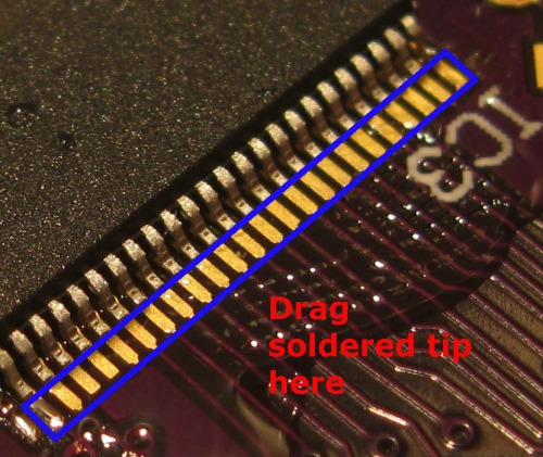
I had read somewhere when populating a SMD you should start with the largest component and work down to the smallest. That’s what I did. I started by trying to pin the Atmega chip to its pads. In the end, I used the dragging tip method with plenty of solder flux.
I had also invested in one of these do-hickies so I could check all my pins. I hate the way it looks, but it saved me so many times I don’t care.
I put the board on my helping hands and after a lot of flux and around 45 minutes; I learned how to tack the corners with a little solder and then use the drag and drop method. I believe that .022” solder is key here. It allowed me to better control the little solder it takes to connect the pads. One thing I noticed, when using the drag across method, put the solder on your tip and just touch the edge of the pad, not the leg of the pin. As long as your iron is hot enough, the solder will flow on its own up the pad based on the meniscus effect.
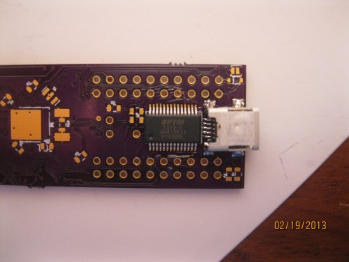
Once I got the Atmega in place it only took another 20 minutes to get all the other pieces on the board. No hurdles worth mentioning. Well, the heat slug on the voltage regulator was a little tricky. But I ended up putting solder down on the pad, keeping my iron tip in it, I used tweezers to press the back of the regulator down against it and slide my solder tip out as I did. Not beautiful, but it worked.
The complete parts list for the Mega Mini is follows:
16mhz SMD Resonator (Digikey 490-1198-1-ND): $.48
USB Serial UART 28 SSOP (Digikey 768-1007-1-ND): $4.50
Mini USB 2.0 (Digikey H2959CT-ND): $1.38
Atmega 2560-16UA: $12.38-17.00
8 x 100nf – 0805 Capacitors: $.08
2 x 10uf – 0805 Capacitors: $.02
1 x 10k Resistor: $.01
4 x Uknown Resistors (I used 100k, I believe): $.04
5V Voltage Regulator LDO (Digikey NCP1117DT50RKGOSCT-ND): $.49
Last piece soldered! Now I’ll I needed to do was plug it in and then it worked, right?
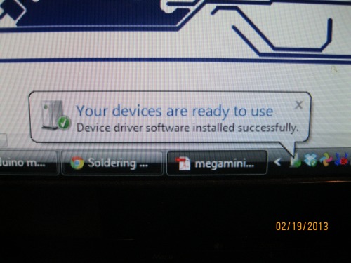
I ran to the computer and plugged my board in. I was thrilled to hear a “Doo-dooh!” USB connection sound and then this pop on my screen.
“Your devices are ready to use”
My ass it was!
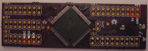
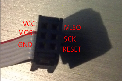
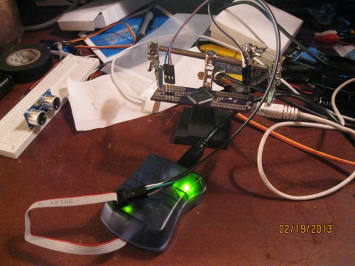
This is where my second hell began. I had bought my AVR ISP MKII to do the programming. After about twenty minutes of going through the pinout I had my interface setup.
Now that I had it connected. I brought up my Atmel Studio 6. I switched over to the “Device Programmer” selected my programmer, then I selected my chip as “Atmega 2560” (this covers all variants of the 2560). I then hit the “Read” under Device Signature. It shot back telling me there wasn’t anything there. I read the voltage, it was fine at 5.1v. I then took the board over and used my hideous spectacles to scoured the board for mistakes I made. One thing I should mention: I had to guess at a few resistors on the board. The designer hadn’t put their values in schematic. So, I felt for sure that was what it was. Then I looked down to my helping hand clipped to the board–I thought, “Huh. I wonder if something is shorting out on the unhelping hand.” Moved the hand. Hit “Read” again. Guess what? If you buy a metal Helping Hands, make sure it’s not shorting you board. My board signature was reading. Now, I just had to figure out how to program it. I ran all over Arduino.cc, AVRfreaks, and Lady Ada’s forums looking for how to program an Atmega 2560. I found a few posts, but it seemed everyone was more interested in programming Atmega 328 DIP packages. Pfft.
Therefore, out of lack of patience I made a mistake I’ll wear to remind me to think three times before acting once. **I messed with the fuses. **Mind you, I did according to a rather knowledgeable sounding post on Arduino.cc. However, it bricked my board.
Mother-of-some-puppies!
Dante had his Inferno and Purgatorio; I have Etching 8mil and Atmel Fuses.
I went to bed. Got up. Went to work. Helped some homeless people. Tried not to think about my huge blunder. But by the time I got home I knew what I had to do. Originally, I had gotten two sampled Atmega 2560-16UA chips from Atmel. I needed to make the second board. This go, the board took me maybe 25 minutes. But I didn’t run over and try to brick it. I waited. I plugged it in and swore to myself not to attempt programing it until I had become an expert on fuses, lockbits, and whatever silly things Atmel had put into such an awesome little chip.
So I read. And read.
Guess what? I’m still just almost as lost.
But I did learn a few things:
Atmel Studio Driver and AVRDude drivers hate each other. They are like Capulets and Montagues.
Fuses are written in hex and define the external and internal qualities of the chip. Such as whether or not it has an external clock, or is running on the internal 8mhz.
No one really messes around with TFQP-100 chips, therefore, I found few people who’d been in my shoes.
Arduino’s IDE automatically sets the fuses when it burns the bootloader. Atmel Studio makes you set them manually.
In the end, I solved my problem the American way! Gut feelings and dumb luck.
I noticed that I could write the Arduino Atmega 2560 bootloader to the board using Atmel Studio. But I couldn’t write it using Arduino’s IDE due to the driver conflict. I tried the family’s computer. I noticed that the Arduino IDE would act like it was writing the bootloader but would sit with the orange light (meaning it was “programming”) on for hours. Then, I noticed something strange after I tried the Arduino IDE to program it on the garage computer running Linux. When I pulled up the fuses page for the board in Atmel studio the fuses had changed. It hit me…maybe the Arduino IDE was successful in writing the fuses but not the bootloader…oh wait! I can write the bootloader from Atmel studio. I ran back to the computer running studio, plugged up the board, and uploaded the bootloader. I said a prayer and plugged just the Mega Mini. I brought up the Arduino IDE and selected the correct COM. I hit “Upload.”
The sketch uploaded. I would have cried but I didn’t want to short the board, or, yanno, seem weak and unmanly.
I quickly uploaded my robot sketch and ran off to have an O’Douls.
Lessons learned:
Etching smaller than 10mil boards is not impossible. But it is not cost effective if time and failed attempts are counted.
Lithography is the easiest method, with the highest resolution, for two-sided circuit boards.
OSHPark is a pretty easy and inexpensive way to get quality boards (with holes drilled and vias run!).
Passion, perserverance, and patience are the virtues of homemade electronics.
Atmel Studio and AVRDude drivers for the AVR ISP MKII conflict.
Atmel chip fuses are not toys.
One should never attempt to use loupe glasses and solder at the same time. You’ll burn your hair–trust me.
A great way to learn something great, is to recognize greatness in others, immitate it, then make it your own. I’ve already seen how I will change the Mega Mini to meet my needs. I don’t really care for FTDI chips on boards. It doesn’t make sense to me. They are $4.50. I’d rather put the serializer on the cable. Because I’ve become initimate with the layout of this board, I know I can redesign it to remove the usb connector and FTDI (saving $5.00 a board).
If you plan on making fewer then around 7 boards, it is not cost effective to make them yourself. JKDevices sell them for $45.00 and the break even point by my calculations is 6.43 (see chart at bottom). I hope that doesn’t discourage anyone. Price is only one way of looking at it. I cannot put a price on everything I’ve learned in the process.
Plans for future:
Make a motor shield for the Mega Mini.
Include M3 (Mega Mini Motorshield) and the Mega Mini into my bot. I believe this will reduce the over bulk of my bot greatly.
Rework the Mega Mini design and remove the FTDI and USB bits. This will reduce the overall cost of the board by $5.88, bringing the price to produce one down to $16.92. Not too shabby.
Look into F. Scott Fitzgeralds’ take on electronics.
Breakeven analysis:
Links to making homemade PCBs:
http://www.artemlive.com/cgi-bin/news?c=v&id=750
http://www.artemlive.com/cgi-bin/news?c=v&id=751
http://en.electroni-city.com/
http://www.youtube.com/watch?feature=endscreen&NR=1&v=p2kFazl-aEE (ok introduction to lithography).
I will update with “4.x” build. But wanted to get video up as demonstration of concept. SSH–>RPi–>I2C Optoisolator–>Arduino Mini Pro—>Self Designed Motor shield–>Tracks :)
This is my first robot. Of course, he is very modular. I’m alright with that–I’m a homeless outreach worker and this entire projects was simply meant to take my mind off the bad stuff for a bit.
I do love this little guy though, his general hodge-podge appearance reminds me of Tank Girl’s monster–good flick.
The Goals:
1. Stay mentally healthy through the Zen of Robotics.
2. Help my two-year-old son overcome his innate fear of robots.
3. To design a platform I could, eventually, use my understanding of psychology and statistics to create nifty behaviors.
The Build v1.x:
In this iteration I have an Interia lab’s base kit (http://www.robotmarketplace.com/products/IL-ANTKIT2.html). I wouldn’t buy the kit again–the tread hubs are too blinkin’ flimsy and the treads fall apart pretty quick (although, the grip on those treads are amazing, it felt like the bugger could climb straight up a wall). Though, the little motors I’m in love with. When I build my next bot, I’ll design my own base, but I’m sure I’ll use these motors (http://www.robotmarketplace.com/products/IL-GMS100.html). Awesome power in such a little package.
The batteries are left over from an old Cannon camera. I have them wired in parallel feeding 8.4v and 2900mAh.
Next, I have an Arduino Uno.
Then, I have an Arduino Motor Shield. I originally was determined to build my own motorshield. I learned about iron transfers, home PCB etching, Eagle, and different sorts of H-Bridge ICs, all which I’ll write about later, but I came to the conclusion I was being delusional about my current level of ability. Therefore, I bought a motorshield and proceeded with the build.
Next, I have a little 5v Linear Regulator (I found out the hard way that if voltage is provided to the Arduino through the vin that apparently a short-circuit is created when you try to draw current from the 5v pin, send it through a sensor, and feed it back into an analog pin. Pfft. And magic smoke from Arduino number #1. It was pretty blue.)
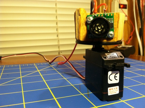
An top of that, I have a block of wood, cut with a hack saw from our garage. Don’t worry, the garage is still standing: um, so far. I put a MaxSonar sensor on it (https://www.sparkfun.com/products/639). I’ve enjoyed this robust sensor; we even survived the short-circuit vin scenario together.
I also have a vibration sensor wired with a 1 meg resistor (https://www.sparkfun.com/products/9196) feeding into analog pin.
And, of course, a feedback LED.
1.x Video
The Build v2.x:
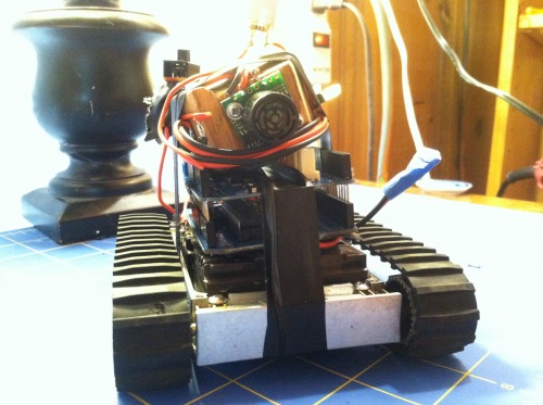
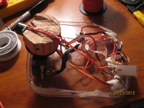
I felt I had finally assembled the “kit.” But I wanted to own it. I wanted to get rid of the electrical tape holding the whole thing down. I made this little mess. I took some plexi and cut a hole in the middle, then put a slit down some poly-flex tubing and hot glued around the edge as bumper. I used a medium servo and threaded through the hole for the MaxSonar. I found some flexible wire that had enough give to keep from the wire breaking down. Last, hot glue and semi-firm putty held the other bits in place. I felt like I “owned” it a little more now–and the whole thing worked pretty great, except how I chose to mount the servo. The MaxSonar sensor stuck over the edge and would bump into things first.
Another thing I noticed, the plateform I had created worked nicely as a handle for Silas, my son. This led him to play with the bot a little more–even “saving” him a few times.
2.x Video (Be warned, baby in diaper.)
The Build 3.x
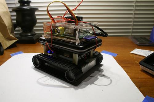
I wanted to own more of my build; I procceeded to cut plates using Home Depot grade Plexiglass and long ago I bought a pair of Xbees to be used in a projects. I decided that until I had the kinks worked out in my platform, I would make a simple Xbee controller using Processing 2.0. I removed all the electric tape and pulled out LSN’s guts. I cut several Plexiglass plates to act as component holders.
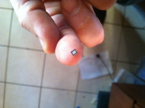
One plate to cover the base, which I glued two 3 AA battery holders. I put these in parellel, using 3 LiFePo4 600 mAh batteries. I ended up with 9.6v at 1200 mAh LiFePo4. I had found the batteries at Wal-Mart on sale and bought them with the intention of learning how to make my own battery packs. Unfortantely, it has been more of a challenge than I expected; no easy charger setup, so I found some chips to charge them in series and I bought the chips thinking I could etch a board real easy like and make my own chargable pack. Well, I didn’t check what chip I was getting and ended up with a DFN that was approaching singularity in size (http://ww1.microchip.com/downloads/en/AppNotes/01276a.pdf). I didn’t give up on a charger board–but I knew it was going to take me longer than I wanted (I’ve included my current board verzion, a little more work and I’ll send it off to OshPark).
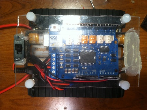
Next, I cut a plexiglass template for the Arduino and Motor Shield, lastly, I cut a plexiglass template and cut out where the pins from the an Arduino Wireless Shield could sit down into the Motor Shield. I secured all this down with some 3 inch aluminimum stand offs and some plastic screw knobs (obtained from Alliedelec.com). I screwed the stand offs into the closure mounting holes.
As I mentioned wanting to earlier, I removed the servo and MaxSensor; in place, I put a breadboard for testing sensors.
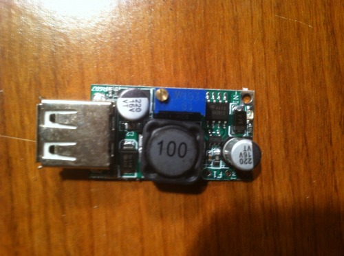
To power the sensors, I replaced the 5v linear voltage regulator with this neat little DC-DC regulator (LM2596). The little trim pot lets you set the output 1.5v to 35v, 2A (input is 4.5v-40v). And it made me happy at $1.56 on eBay. I also notched out the plexi and put a little two-state switch for turning the bot on and off.
Of course, the sensor I actually worked into the code of this build was simply a HC-SR04 stuck percariously into the breadboard. (I didn’t want to pull the MaxSonar out of the rather stable block of wood I had it screwed on.)
The Build 4.x
.
The Code v1.x:
The basic code tells the little guy to run around shooting his sonar everywhere. If he detects something closer than 12 inches, he stops, turns to the right, takes a reading, turns to the left, reads, then compares the three readings. Front, left, and center, whichever is more clear he’ll start going that direction. He does this ad infinitium–or ad batterius-lowus. If the little guy miss reads, or the sonar’s beam wasn’t wide enough, he’ll run into something and activate the knock sensor. If this happens, he backs up, does a 180 and starts again.
I did have the foresight to design the code around function calls (e.g., “Forward()”) so that I could eventually give him a big brain using some sort of RF connection (later, I think it will be a PC and Python).
The Code 2.x
This code is pretty close to the original; I added the servo functions and I think a few other minor tweaks (most which I tried to annotate throughout my code).
The Code 3.x
As I mentioned in the build–I had bought a pair of Xbees to incorporate into a motioned driven bellydance skirt for my wife. Fortunately, I found a better way to build it, so I left me with two Xbees Ser1’s. After a little meditating, I realized I was finally reaching the point where I could begin to write code on some of processing unit and start doing nifty things with the little guy. So, I chose to start in Processing, since it was close to the code I was familiar. After a bit, I had written a rather rough draft of a simple RC controller using a PC, Processing, and the Xbees (Zombie_Processing_3_6_RC.zip).
But, that wasn’t good enough for me. I had bought a Raspberry Pi that I desperately wanted to add on to the bot. I had done the math. I figured that it was almost as much to setup a RPi with a WiFi dongle as it was to buy a WiFly.
WiFly setup:
WiFly Xbee from SparkFun: $42.95
Arduino WiFi Shield: $6.98
Total for WiFly: $49.93
Basic Raspberry Pi and WiFi Dongle
WiFi Dongle: $6.17
Raspberry Pi: $35.00
SD Card (4g): $2.50
Total for Basic RPi: $43.67
My delusional mind, obviously ahead of my ability, began to run through how this RPi setup would look. I began to see my little bot as having two separate components to its existence. The RPi would be the central nervous system and the Arduino would be the peripheral. The Arduino would be tasked with executing movement and perception functions and the RPi would be tasked with computation and analysis. So, with my inability to see my inability, towards the end of writing the Processing code to act as controller I realized that it would be a good place to begin testing the peripheral nervous system (Arduino code) of my little bot. Moreover, that when I did finally reach the point where I was skilled enough to write intelligent code, then that code would replace the my commands sent from Processing.
Of course, a problem hit me upside the head–” By default, we’ll be supporting Python as the educational language.” F’ing RPi makers. Oh well–I’d been needing to learn another programming language. Well, after several days of delving into a scripting language (it was friggin like trying to speak Koiné of the Late Empire) I finally pieced together working(?) Python code. The Python code I wanted to act as the equivalent to my Processing code, which to my surprise, it did. So, I was able to leave my Arduino sketch the very same, i.e., my Python script and Processing code will both work on the same version of Arduino sketch.
I did notice the potential of Python. I was capable of incorporating threading and Tkinter’s gui.
I would like to indulge in a caveat. These codes are in no way complete–I’ve simply put my mind towards some mechanical projectss while I wait for the components to come in needed to finish.
The Code 4.x
The code for this version might seem somewhat complicated, but after your under the hood (or bonnet, for my European friends) then it actually is much simpler than my Xbee build.
The information flow can be summed up like so:
SSH —> Raspberry Pi —> I2C Optoisolator –> Arduino Pro Mini –> M3 Motor Shield
In essence, it’s a Raspberry Pi WiFi Dongle.
I designed the flow this way so that I could program higher-level functions (e.g., sensor data computation) on the Raspberry Pi, thereby allowing me to make it autonomous by replacing my keystrokes with its own choices (I hope they’re good choices). Of course, this would still allow me to SSH into my Python code on RPi to tweak as I needed.
Therefore, the eventual information flow will be like so:
Raspberry Pi —> I2C Optoisolator –> Arduino Pro Mini –> M3 Motor Shield.
I’ll do my best to out line my code and resources needed to get the code working.
First off, setting up the RPi.
Instead of including in this build, I made a separate walking through.
The code is actually pretty simple right now. The Python comes up with something to do (right now generated from keystrokes) and tells the Arduino to do it. It does this by capturing keystrokes, converting them to byes, sending them over the I2C bus where the Arduino captures them, translates them back from bytes into something human readable. Each keystroke then is associated with a routine. If it captures the “W” key code, it turns it into bytes, over I2C, Ardy grabs it, turns it back into a “W,” then runs the Forward() function. Likewise, the Arduino can send information back through the bus to the Pi, which the Pi converts from a byte, into character, then compiles the characters into a string until it predefined delimiter. Simple.
The keystroke will eventually be replaced with Raspberry Pi calculations–therefore, it’s the central nervous system. The Arduino will be responsible for carrying out functions; in this metaphor, it’s the autonomous nervous system. The idea is, even if the Pi goes down, the Ardy will hold on to some basic functionality. This allows the synergy of high-functions (e.g., speech synthesizing) and system stability (Arduino’s “survival code”). Of course, it’s not done yet. :)
Dicussion v1.x:
So, I’m actually much further with this guy now. But I felt I should go back and verbally process my build; keeping track of it for my sake, and perhaps any other hack like me unfortunate enough to read this.
Therefore, I’m going to list the things I’ve learned (those bored are welcome to leave quietly).
The LMR collective is invaluable–(although, they can be a little Ayn Randish with inepts, **“You didn’t ‘Google’ that question before posting! Stick-piggie-piggie! Stick!” **Especially that Cristal the Carpenter fellow).
SparkFun is EXPENSIVE.
Ebay is cheap.
Magic smoke smells good.
Designing a circuit is easy; designing a good circuit is esoteric. Although, I still believe I did the right thing in trying to design my own motor circuit. I learned so much from digging around in datasheets and online tutorials, although the frustration was high, the knowledge I gained was worth it.
Etching your own boards is pretty easy. Trying to etch a board with small traces is a mother-of-some-puppies.
When making homemade PCBs, get a good soldering iron. Cheap irons don’t seem to get hot enough. What ended up happening to me was when the tip got a little dirty I’d go to solder a pin and as I was pulling my iron away the trace would come off the board. Funny enough, this is most likely to happen on the very last pin you solder. Not sure why.
Although I now feel comfortable building my own bot from raw components, I’m not ashamed I built this iteration from modular components. It has taught me a lot.
Electronics fills your mind. The zen of robots has been excellent for my mental health.
Being delusional is in a maker’s best interest. Dream it, start building, and when the details hit you in the face, hit back with a lot of creativity. And remember, you always have Grandma Google to explain anything you might need to know.
RC cars are for jocks; robots are for the awesome.
Discussion v2.x
Looking back, I’m not sure I would have gone with the servo again. I didn’t analyze the current it drew, but I’m pretty sure it wasn’t that much less than firing the motors and having the entire bot shift. The treads gripped well, so I don’t feel like I would have sacrificed any precision. I would simply have the bot zero-point turn to the right, left, instead of the servo. Not sure why, my gut was happier with fewer moving parts–before the servo the build had a more solid feel to it. But, on the plus side, I did learn to use servos through the process. I also learned the hard way the differences between a degree rotation servo and a full rotation servo.
Lessons learned:
Dremel tools are a necessity for robot building. Especially cutting bits.
A table vice is nice. So is a real workbench (even if it came out of a dumpster).
A full-rotation servo is not precise (I know angular servos are not either, but I’m not looking for reductio ad absurdum).
Children think servos are make creepy noises.
Plexiglass is great for prototyping. Combined with a dremel, cutting bits, and a speed-square, rapid prototyping has never been so ghettotastic.
Discussion 3.x:
I’m very excited to begin approaching the put where I can put some real brains into the little guy. Looking back, I will feel a twinge of regret not begining the Xbee controller code in Python rather than writing it in Processing and then re-writing it in Python. Regardless, it was good practice. Also, I know the kinks I will need to work out for a stable version of this Xbee controller. Right now, the processing code has little error control–when receiving data, it simply draws it from the Arduino and displays it. It doesn’t worry about dropped bits or unusable data. The Python code has sophisticated error checking on par with an amoebae. Right now, it simply checks to see if the readline has more than 8 or 9 digits to it. If it does, it prints the data, if not, it skips and waits for a more complete readline. These can be improved drastically. But, it simply isn’t my intention to do so. Eventually, I plan to place the Raspberry Pi on top of the Arduino, linked with a USB cable. So, I’m really counting on no data lost to the aether. I wrote these codes simply to see if I could. Like a caveman grunting his prowess to a robot.
Discussion 4.x
I feel I’ve created probably one of the most complex RC cars on the internet. And I’m tired.
Lessons learned:
Raspberry Pi’s have pull-up resistors on their I2C lines.
“Typical application” schematics in datasheets are amazing.
Don’t rely on copying others work. Create your own, it is much more satisfying.
Delusions are good.
I’m not smart, I’m obsessive.
I2C is simpler than serial?
Those quick2wire guys are full-of-shinobi.
Designing OSHPark boards has the added benefit of encouraging you to be efficient about PCB design, since you are charged by the square inch. It pays to learn to design compact boards, with SMD parts.
It’s not Python that annoys me, rather, it is the lack of ways to manage Python version compatibility.
COGs Breakdown 1.x:
Interia’s base (4 motors, treads, hubs, and CNC’ed aluminum): $109.00
Arduino Uno: $34
Arduino Motor Shield: $28
Knock Sensor: $2.95
MaxSonar: $25.95
Batteries: Already got’em. Est. $12.95
Medium Servo $10.95
Total: $223.80
COGs Breakdown 2.x:
Interia’s base (4 motors, treads, hubs, and CNC’ed aluminum): $109.00
I’ve tons of projects. Too many. Ironically, I’m a goal oriented person. I thrive on completing something cool. And as I get older I begin to realize, time is my greatest enemy. I don’t have the time I need to complete as many projects as I scheme. Here is my attempt to reign in the number of projects, choosing to focus on what matters.
Here’s what matters to me:
Family
My family matter most. This is complicated, because my brain needs breaks from them. But if there is a project which will enable engagement with my family, it should take priority.
Interest
Part of the reason I’m in this project swamp is my natural curiousity. I’m largely a determinist. I believe what you do, regardlesss of your initial interest level, will eventually become interesting.
Learning
I once wrote in a college essay: “If you’re not learning, you’re dying.” Still not sure of the veracity of the statement, but I’ve lived by it since writing it. I’ve fallen in love with learning–I want to make sure the projects I work on are actually helping me learn. Not actions to grind through an activity.
Kudos
Being real, I like when people think my work is interesting. The longer I spend in the development world, the more I realize this is pretty universal among good developers. They care about what they produce and enjoy when someone appreciates it.
Helping Others
I don’t know a lot, but I know people have absolute worth. Human beings, regardless if they are spiritual vessels or evolutionary by products, are absolutely amazing. I enjoy getting opportunities to help others.
Lolz
I see value in walking an unbeaten path. Creating projects which have little value to others, but bring me joy, are worth working on to me.
Automation
Definition of “Done”
Nothing gets started until there’s a definition of done.
Projects
Name
Family
Interest
Learning
Kudos
Helping
Lolz
Total
Write Python package for intereacting with RAMPs
1
1
1
1
4
Writing a BLE bleak terminal article.
1
1
1
1
4
Write article on Bluetooth LE using the ESP32
1
1
1
1
4
Develop a ML model for predicting length of homelessness
1
1
1
1
4
Write Self-Sensored iOS app
1
1
1
3
Create REST API for SelfSensored using Flask
1
1
1
3
Implement DDS with Arduino and RAMPs
1
1
1
3
Creating lessons for teaching Silas to program.
1
1
2
Create REST API for SelfSensored using AWS Gateway
1
1
2
Pull data from Trello
1
1
1
3
Modify Flask, uWSGI, MariaDB stack script for HTTPs

 **
**
 **
** **
**
 Now that I had it connected. I brought up my Atmel Studio 6. I switched over to the “Device Programmer” selected my programmer, then I selected my chip as “Atmega 2560” (this covers all variants of the 2560). I then hit the “Read” under Device Signature. It shot back telling me there wasn’t anything there. I read the voltage, it was fine at 5.1v. I then took the board over and used my hideous spectacles to scoured the board for mistakes I made. One thing I should mention: I had to guess at a few resistors on the board. The designer hadn’t put their values in schematic. So, I felt for sure that was what it was. Then I looked down to my helping hand clipped to the board–I thought, “Huh. I wonder if something is shorting out on the unhelping hand.” Moved the hand. Hit “Read” again. Guess what? If you buy a metal Helping Hands, make sure it’s not shorting you board. My board signature was reading. Now, I just had to figure out how to program it. I ran all over Arduino.cc, AVRfreaks, and Lady Ada’s forums looking for how to program an Atmega 2560. I found a few posts, but it seemed everyone was more interested in programming Atmega 328 DIP packages. Pfft.
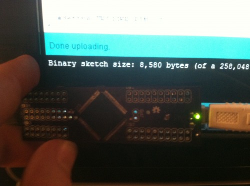

