Originally posted on www.letsmakerobots.com
I will update with "4.x" build. But wanted to get video up as demonstration of concept. SSH-->RPi-->I2C Optoisolator-->Arduino Mini Pro--->Self Designed Motor shield-->Tracks :)
This is my first robot. Of course, he is very modular. I'm alright with that--I'm a homeless outreach worker and this entire projects was simply meant to take my mind off the bad stuff for a bit.
I do love this little guy though, his general hodge-podge appearance reminds me of Tank Girl's monster--good flick.
The Goals:
1. Stay mentally healthy through the Zen of Robotics.
2. Help my two-year-old son overcome his innate fear of robots.
3. To design a platform I could, eventually, use my understanding of psychology and statistics to create nifty behaviors.
The Build v1.x:
In this iteration I have an Interia lab's base kit (http://www.robotmarketplace.com/products/IL-ANTKIT2.html). I wouldn't buy the kit again--the tread hubs are too blinkin' flimsy and the treads fall apart pretty quick (although, the grip on those treads are amazing, it felt like the bugger could climb straight up a wall). Though, the little motors I'm in love with. When I build my next bot, I'll design my own base, but I'm sure I'll use these motors (http://www.robotmarketplace.com/products/IL-GMS100.html). Awesome power in such a little package.
The batteries are left over from an old Cannon camera. I have them wired in parallel feeding 8.4v and 2900mAh.
Next, I have an Arduino Uno.
Then, I have an Arduino Motor Shield. I originally was determined to build my own motorshield. I learned about iron transfers, home PCB etching, Eagle, and different sorts of H-Bridge ICs, all which I'll write about later, but I came to the conclusion I was being delusional about my current level of ability. Therefore, I bought a motorshield and proceeded with the build.
http://cthomasbrittain.wordpress.com/2013/01/27/design-a-motor-driver-for-lsn-bot/
Next, I have a little 5v Linear Regulator (I found out the hard way that if voltage is provided to the Arduino through the vin that apparently a short-circuit is created when you try to draw current from the 5v pin, send it through a sensor, and feed it back into an analog pin. Pfft. And magic smoke from Arduino number #1. It was pretty blue.)
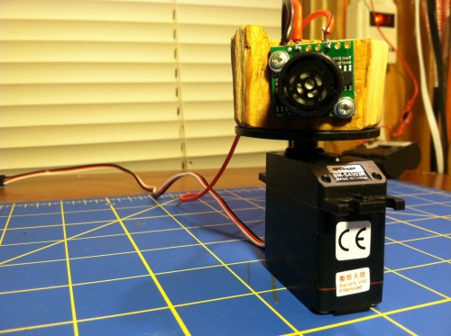
An top of that, I have a block of wood, cut with a hack saw from our garage. Don't worry, the garage is still standing: um, so far. I put a MaxSonar sensor on it (https://www.sparkfun.com/products/639). I've enjoyed this robust sensor; we even survived the short-circuit vin scenario together.
I also have a vibration sensor wired with a 1 meg resistor (https://www.sparkfun.com/products/9196) feeding into analog pin.
And, of course, a feedback LED.
1.x Video
 The Build v2.x:
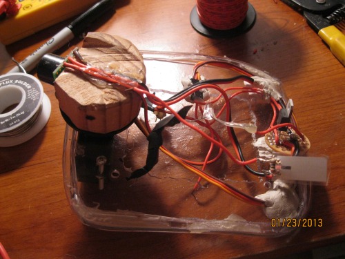
I felt I had finally assembled the "kit." But I wanted to own it. I wanted to get rid of the electrical tape holding the whole thing down. I made this little mess. I took some plexi and cut a hole in the middle, then put a slit down some poly-flex tubing and hot glued around the edge as bumper. I used a medium servo and threaded through the hole for the MaxSonar. I found some flexible wire that had enough give to keep from the wire breaking down. Last, hot glue and semi-firm putty held the other bits in place. I felt like I "owned" it a little more now--and the whole thing worked pretty great, except how I chose to mount the servo. The MaxSonar sensor stuck over the edge and would bump into things first.
Another thing I noticed, the plateform I had created worked nicely as a handle for Silas, my son. This led him to play with the bot a little more--even "saving" him a few times.
2.x Video (Be warned, baby in diaper.)
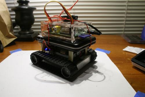
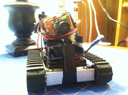
The Build 3.x
I wanted to own more of my build; I procceeded to cut plates using Home Depot grade Plexiglass and long ago I bought a pair of Xbees to be used in a projects. I decided that until I had the kinks worked out in my platform, I would make a simple Xbee controller using Processing 2.0. I removed all the electric tape and pulled out LSN's guts. I cut several Plexiglass plates to act as component holders.
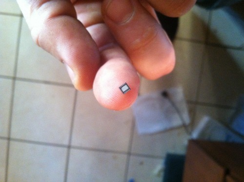
One plate to cover the base, which I glued two 3 AA battery holders. I put these in parellel, using 3 LiFePo4 600 mAh batteries. I ended up with 9.6v at 1200 mAh LiFePo4. I had found the batteries at Wal-Mart on sale and bought them with the intention of learning how to make my own battery packs. Unfortantely, it has been more of a challenge than I expected; no easy charger setup, so I found some chips to charge them in series and I bought the chips thinking I could etch a board real easy like and make my own chargable pack. Well, I didn't check what chip I was getting and ended up with a DFN that was approaching singularity in size (http://ww1.microchip.com/downloads/en/AppNotes/01276a.pdf). I didn't give up on a charger board--but I knew it was going to take me longer than I wanted (I've included my current board verzion, a little more work and I'll send it off to OshPark).
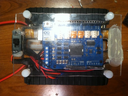
Next, I cut a plexiglass template for the Arduino and Motor Shield, lastly, I cut a plexiglass template and cut out where the pins from the an Arduino Wireless Shield could sit down into the Motor Shield. I secured all this down with some 3 inch aluminimum stand offs and some plastic screw knobs (obtained from Alliedelec.com). I screwed the stand offs into the closure mounting holes.
As I mentioned wanting to earlier, I removed the servo and MaxSensor; in place, I put a breadboard for testing sensors.
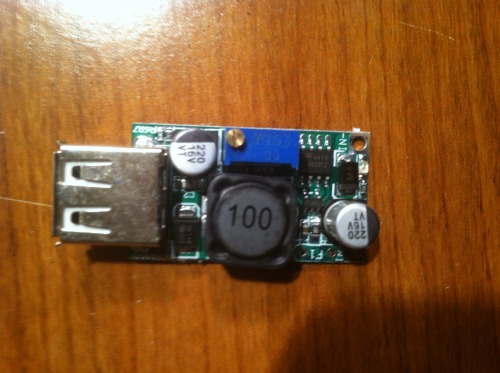
To power the sensors, I replaced the 5v linear voltage regulator with this neat little DC-DC regulator (LM2596). The little trim pot lets you set the output 1.5v to 35v, 2A (input is 4.5v-40v). And it made me happy at $1.56 on eBay. I also notched out the plexi and put a little two-state switch for turning the bot on and off.
Of course, the sensor I actually worked into the code of this build was simply a HC-SR04 stuck percariously into the breadboard. (I didn't want to pull the MaxSonar out of the rather stable block of wood I had it screwed on.)
The Build 4.x
.
The Code v1.x:
The basic code tells the little guy to run around shooting his sonar everywhere. If he detects something closer than 12 inches, he stops, turns to the right, takes a reading, turns to the left, reads, then compares the three readings. Front, left, and center, whichever is more clear he'll start going that direction. He does this ad infinitium--or ad batterius-lowus. If the little guy miss reads, or the sonar's beam wasn't wide enough, he'll run into something and activate the knock sensor. If this happens, he backs up, does a 180 and starts again.
I did have the foresight to design the code around function calls (e.g., "Forward()") so that I could eventually give him a big brain using some sort of RF connection (later, I think it will be a PC and Python).
The Code 2.x
This code is pretty close to the original; I added the servo functions and I think a few other minor tweaks (most which I tried to annotate throughout my code).
The Code 3.x
As I mentioned in the build--I had bought a pair of Xbees to incorporate into a motioned driven bellydance skirt for my wife. Fortunately, I found a better way to build it, so I left me with two Xbees Ser1's. After a little meditating, I realized I was finally reaching the point where I could begin to write code on some of processing unit and start doing nifty things with the little guy. So, I chose to start in Processing, since it was close to the code I was familiar. After a bit, I had written a rather rough draft of a simple RC controller using a PC, Processing, and the Xbees (Zombie_Processing_3_6_RC.zip).
But, that wasn't good enough for me. I had bought a Raspberry Pi that I desperately wanted to add on to the bot. I had done the math. I figured that it was almost as much to setup a RPi with a WiFi dongle as it was to buy a WiFly.
WiFly setup:
- WiFly Xbee from SparkFun: $42.95
- Arduino WiFi Shield: $6.98 Total for WiFly: $49.93
Basic Raspberry Pi and WiFi Dongle
WiFi Dongle: $6.17 Raspberry Pi: $35.00 SD Card (4g): $2.50 Total for Basic RPi: $43.67
My delusional mind, obviously ahead of my ability, began to run through how this RPi setup would look. I began to see my little bot as having two separate components to its existence. The RPi would be the central nervous system and the Arduino would be the peripheral. The Arduino would be tasked with executing movement and perception functions and the RPi would be tasked with computation and analysis. So, with my inability to see my inability, towards the end of writing the Processing code to act as controller I realized that it would be a good place to begin testing the peripheral nervous system (Arduino code) of my little bot. Moreover, that when I did finally reach the point where I was skilled enough to write intelligent code, then that code would replace the my commands sent from Processing.
Of course, a problem hit me upside the head--" By default, we’ll be supporting Python as the educational language." F'ing RPi makers. Oh well--I'd been needing to learn another programming language. Well, after several days of delving into a scripting language (it was friggin like trying to speak Koiné of the Late Empire) I finally pieced together working(?) Python code. The Python code I wanted to act as the equivalent to my Processing code, which to my surprise, it did. So, I was able to leave my Arduino sketch the very same, i.e., my Python script and Processing code will both work on the same version of Arduino sketch.
I did notice the potential of Python. I was capable of incorporating threading and Tkinter's gui.
I would like to indulge in a caveat. These codes are in no way complete--I've simply put my mind towards some mechanical projectss while I wait for the components to come in needed to finish.
The Code 4.x
The code for this version might seem somewhat complicated, but after your under the hood (or bonnet, for my European friends) then it actually is much simpler than my Xbee build.
The information flow can be summed up like so:
SSH ---> Raspberry Pi ---> I2C Optoisolator --> Arduino Pro Mini --> M3 Motor Shield
In essence, it's a Raspberry Pi WiFi Dongle.
I designed the flow this way so that I could program higher-level functions (e.g., sensor data computation) on the Raspberry Pi, thereby allowing me to make it autonomous by replacing my keystrokes with its own choices (I hope they're good choices). Of course, this would still allow me to SSH into my Python code on RPi to tweak as I needed.
Therefore, the eventual information flow will be like so:
Raspberry Pi ---> I2C Optoisolator --> Arduino Pro Mini --> M3 Motor Shield.
I'll do my best to out line my code and resources needed to get the code working.
First off, setting up the RPi.
Instead of including in this build, I made a separate walking through.
The code is actually pretty simple right now. The Python comes up with something to do (right now generated from keystrokes) and tells the Arduino to do it. It does this by capturing keystrokes, converting them to byes, sending them over the I2C bus where the Arduino captures them, translates them back from bytes into something human readable. Each keystroke then is associated with a routine. If it captures the "W" key code, it turns it into bytes, over I2C, Ardy grabs it, turns it back into a "W," then runs the Forward() function. Likewise, the Arduino can send information back through the bus to the Pi, which the Pi converts from a byte, into character, then compiles the characters into a string until it predefined delimiter. Simple.
The keystroke will eventually be replaced with Raspberry Pi calculations--therefore, it's the central nervous system. The Arduino will be responsible for carrying out functions; in this metaphor, it's the autonomous nervous system. The idea is, even if the Pi goes down, the Ardy will hold on to some basic functionality. This allows the synergy of high-functions (e.g., speech synthesizing) and system stability (Arduino's "survival code"). Of course, it's not done yet. :)
Dicussion v1.x:
So, I'm actually much further with this guy now. But I felt I should go back and verbally process my build; keeping track of it for my sake, and perhaps any other hack like me unfortunate enough to read this.
Therefore, I'm going to list the things I've learned (those bored are welcome to leave quietly).
- The LMR collective is invaluable--(although, they can be a little Ayn Randish with inepts, "You didn't 'Google' that question before posting! Stick-piggie-piggie! Stick!" Especially that Cristal the Carpenter fellow).
- SparkFun is EXPENSIVE.
- Ebay is cheap.
- Magic smoke smells good.
- Designing a circuit is easy; designing a good circuit is esoteric. Although, I still believe I did the right thing in trying to design my own motor circuit. I learned so much from digging around in datasheets and online tutorials, although the frustration was high, the knowledge I gained was worth it.
- Etching your own boards is pretty easy. Trying to etch a board with small traces is a mother-of-some-puppies.
- When making homemade PCBs, get a good soldering iron. Cheap irons don't seem to get hot enough. What ended up happening to me was when the tip got a little dirty I'd go to solder a pin and as I was pulling my iron away the trace would come off the board. Funny enough, this is most likely to happen on the very last pin you solder. Not sure why.
- Although I now feel comfortable building my own bot from raw components, I'm not ashamed I built this iteration from modular components. It has taught me a lot.
- Electronics fills your mind. The zen of robots has been excellent for my mental health.
- Being delusional is in a maker's best interest. Dream it, start building, and when the details hit you in the face, hit back with a lot of creativity. And remember, you always have Grandma Google to explain anything you might need to know.
- RC cars are for jocks; robots are for the awesome.
Discussion v2.x
Looking back, I'm not sure I would have gone with the servo again. I didn't analyze the current it drew, but I'm pretty sure it wasn't that much less than firing the motors and having the entire bot shift. The treads gripped well, so I don't feel like I would have sacrificed any precision. I would simply have the bot zero-point turn to the right, left, instead of the servo. Not sure why, my gut was happier with fewer moving parts--before the servo the build had a more solid feel to it. But, on the plus side, I did learn to use servos through the process. I also learned the hard way the differences between a degree rotation servo and a full rotation servo.
Lessons learned:
- Dremel tools are a necessity for robot building. Especially cutting bits.
- A table vice is nice. So is a real workbench (even if it came out of a dumpster).
- A full-rotation servo is not precise (I know angular servos are not either, but I'm not looking for reductio ad absurdum).
- Children think servos are make creepy noises.
- Plexiglass is great for prototyping. Combined with a dremel, cutting bits, and a speed-square, rapid prototyping has never been so ghettotastic.
Discussion 3.x:
I'm very excited to begin approaching the put where I can put some real brains into the little guy. Looking back, I will feel a twinge of regret not begining the Xbee controller code in Python rather than writing it in Processing and then re-writing it in Python. Regardless, it was good practice. Also, I know the kinks I will need to work out for a stable version of this Xbee controller. Right now, the processing code has little error control--when receiving data, it simply draws it from the Arduino and displays it. It doesn't worry about dropped bits or unusable data. The Python code has sophisticated error checking on par with an amoebae. Right now, it simply checks to see if the readline has more than 8 or 9 digits to it. If it does, it prints the data, if not, it skips and waits for a more complete readline. These can be improved drastically. But, it simply isn't my intention to do so. Eventually, I plan to place the Raspberry Pi on top of the Arduino, linked with a USB cable. So, I'm really counting on no data lost to the aether. I wrote these codes simply to see if I could. Like a caveman grunting his prowess to a robot.
Discussion 4.x
I feel I've created probably one of the most complex RC cars on the internet. And I'm tired.
Lessons learned:
- Raspberry Pi's have pull-up resistors on their I2C lines.
- "Typical application" schematics in datasheets are amazing.
- Don't rely on copying others work. Create your own, it is much more satisfying.
- Delusions are good.
- I'm not smart, I'm obsessive.
- I2C is simpler than serial?
- Those quick2wire guys are full-of-shinobi.
- Designing OSHPark boards has the added benefit of encouraging you to be efficient about PCB design, since you are charged by the square inch. It pays to learn to design compact boards, with SMD parts.
- It's not Python that annoys me, rather, it is the lack of ways to manage Python version compatibility.
COGs Breakdown 1.x:
- Interia's base (4 motors, treads, hubs, and CNC'ed aluminum): $109.00
- Arduino Uno: $34
- Arduino Motor Shield: $28
- Knock Sensor: $2.95
- MaxSonar: $25.95
- Batteries: Already got'em. Est. $12.95
- Medium Servo $10.95
- Total: $223.80
COGs Breakdown 2.x:
- Interia's base (4 motors, treads, hubs, and CNC'ed aluminum): $109.00
- Arduino Uno: $34
- Arduino Motor Shield: $28
- Knock Sensor: $2.95
- MaxSonar: $25.95
- Batteries: Already got'em. Est. $12.95
- Medium Servo $10.95
- Wireless Shield: $22.95
- Xbee X2: $45.90
- Xbee Explorer: $10.95
- Plexiglas: $12.98
- Total: $316.58