The Dream
I’ve dreamed of a PCB with everything: uC, H-bridges, PSU, Lipo charger, inductive power collector, and a wirelesss device which would allow wireless uploading to the uC. A platform I could use for robotics and wearable projectss alike. Most of these features I have solved, yet one which I believed to be ever elusive to a hacker is wireless uploading. I’ve had lot of failed attempts, some as painful as writing my own uploader for the LPC1114, others as “simple” as hacking away at the Arduino IDE source. However, I’ve found a combination which brings me a bit of hope: TinySafeBoot, Arduino IDE, and most Atmega and ATtiny Atmel chips.
TinySafeBoot
TinySafeBoot is a pretty neat GPL projects which is around 500 bytes. It is a bootloader which allows selection of any two pins as RX / TX for two-wire communication (it also has a one wire protocol). And it has a serial communication protocol.
TinySafeBoot
The feature which makes TSB such a great choice for wireless bootloading is its serial protocol. Unlike the hardware protocol Arduino uses, serial communication allows the remote device to control the bootloaders workflow without flipping any hardware pins. Contrast with the Arduino’s bootloader (I think it’s optiboot now?) which focuses on resetting the device repeatedly to activate the bootloader.
The hardware approach doesn’t work for quick, remote hardware resets. With the serial lag, the Arduino bootloaders are often comfortably booting an existing program by the time the first byte of a new program is reaching the RX pin. Also, there is no quick (sub 400ms) way to flip pins on my focused wireless devices, the HM-1X and ESP8266. In short, either the Arduino bootloader or software would need to be hacked; neither, which I’ve had the time to do.
There are other chip possibilities. I spent a lot of time trying to write a wireless uploader for the LPC1114. However, I do not yet have the skill level to finish it (I’ve not given up on it). There is also a psychological hangup working with the LPC1114. Its documentation. It is not that the docs for the 1114 are so bad, it is the docs for Atmel (makers of the Arduino heart) are so much better. This makes solving the wireless upload dilemma much more beneficial if it were solved for Atmel chips. Well, at least for a hacker like me who does not yet have the skill to move quickly through rougher documented chips. Honestly, it’s about time–I’ve only so much and sometimes it is about getting a projects finished rather than what I might learn (blasphemy, right?).
Of course, TSB has other features such as auto-bauding and password protection, etc. It’s not perfect, but I like it for its simplicity.
Getting TSB Setup
I have tested TSB on three devices, the ATtiny85, ATmega328P, and ATtiny1634. However, the ATtiny1634 didn’t work.
There are two parts to TSB,
- Firmware
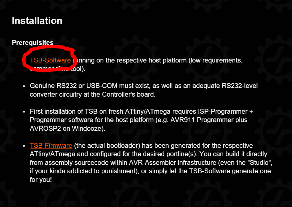
- Software
We are only going to download the software which allows you to generate “custom” firmware for whatever chip you are targeting.
From here on I will be demonstrating getting TSB going on an ATtiny85.
ISP
First, we will need an AVR ISP. Long ago I bought an AVR-ISP MKII which I used in combination with Atmel Studio 7. This will allow us to burn the bootloader and set the fuses. If you do not have an official AVR-ISP you can, theoritically, use AVRdude through the Arduino IDE in combination with an Arduino as an ISP programmer.
So, either,
- AVR ISP MKII
- Atmel Studio 7
Or
- Arduino IDE
- Arduino Uno ISP
Either way, once we have our ISP setup we will connect it to the ATtiny85 like,
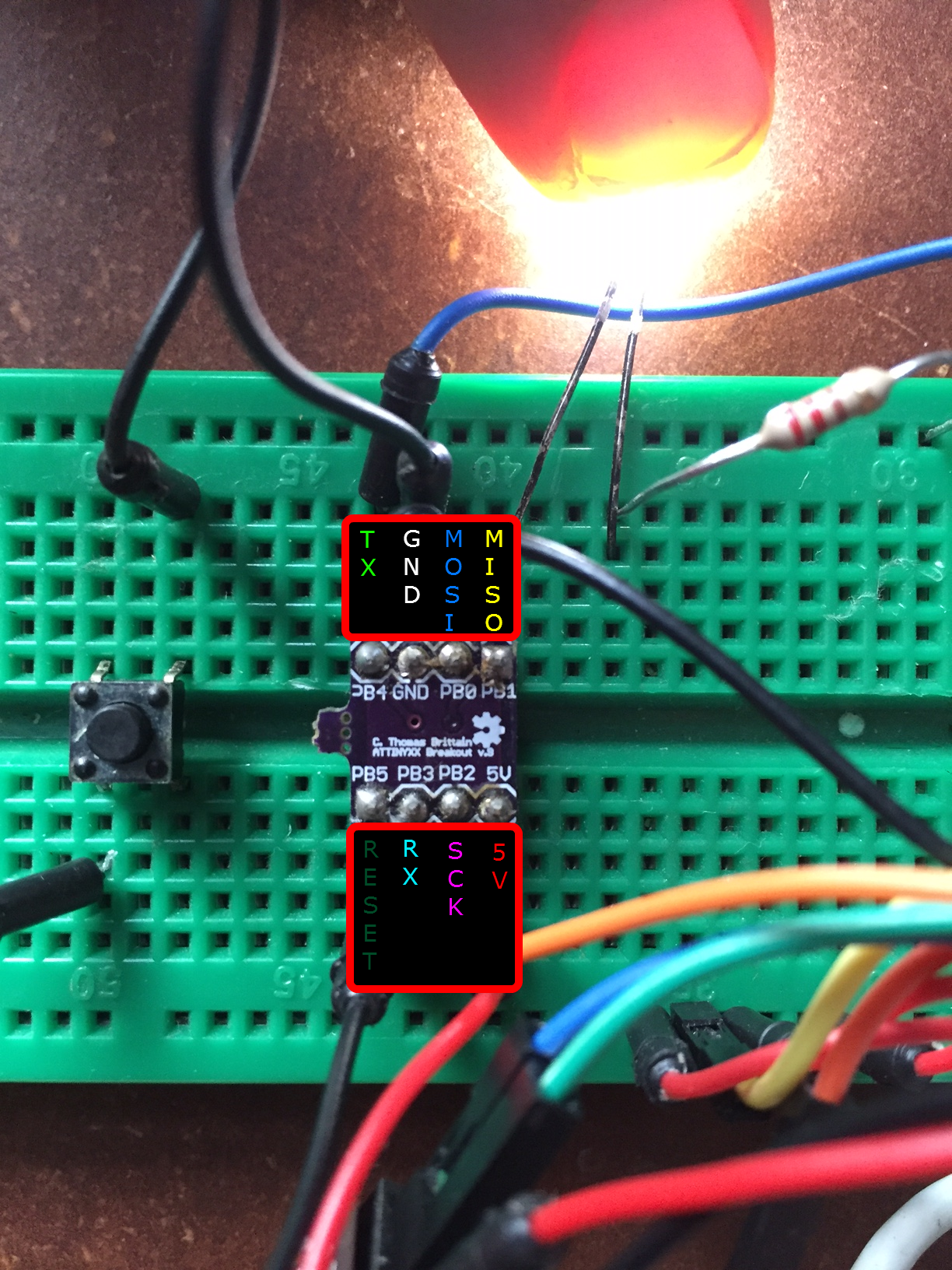
One note about the above breadboard. There is a momentary switch connected in series with the RESET pin,
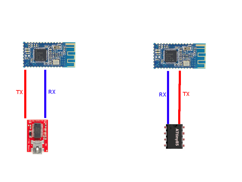
PB5<--->Switch<--->GND
This will allow us to easily reset the ATtiny85, which is needed to put the TSB into bootloader mode.
Notice the RX / TX will. They are not part of the ISP. They will be our bootloader’s TX / RX pins when the bootloader has been burnt.
Bootloader Creation
Now, to generate the bootloader.
If you haven’t, download the software, extract it to a workspace, and open that workspace in the command-line. The TSB software is CLI only.
Now enter the following,
C:\TSB_workspace>tsb tn85 b3b4
TSB then should generate a hex file titled something like,
tsb_tn85_b3b4_20150826.hex
This hex file will be our bootloader customized for our particular AVR, the ATtiny85.
To breakdown the TSB command,
tn85 tells the TSB SW we are looking to install this firmware on an ATtiny85. If you need to look up a chip code you can find it in a file in the TSB workspace titled “devices.txt”b3b4 tells the TSB SW you want to use PB3 as RX and PB4 as TX. I chose these as pins since they are not being used by the ISP. Note, having the ISP and UART connected to the same pins will cause problems.
Bootloader Burning
To burn the newly generated bootloader you will need to have your ISP connected to the ATtiny85. First, check the fuses of your chip. According to the TSB website we need to have the following fuses set,
ATtinys:
- SELFPRGEN must be set to enable flash writes from firmware, e.g. TSB
- BODLEVEL should be set to avoid flash corruption during unsafe device power-up.
- LOCKBITS may be set to MODE 3 for enhanced security (i.e. serious password protection intended).
ATmegas:
- BOOTRST activated lets the MCU jump into the Bootloader Section (rather than $0000) with every hardware Reset.
- BODLEVEL should be set to avoid flash corruption during unsafe device power-up.
- BOOTSZ=10 or BOOTSZ=11 to reserve 512 bytes for a Bootloader Section.
- BLB to MODE 2 or 3 protects Bootloader Section from undesirable write access by firmware.
- LOCKBITS may be set to Mode 3 (LB-Mode 3) in a security environment.
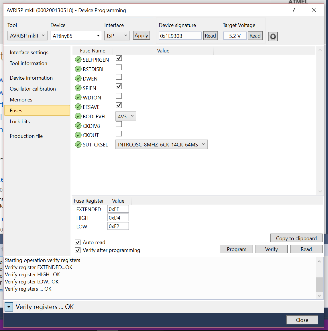
Using Atmel studio, go to Tools-->Device Programming select your programmer (AVR ISP MKII for me), select the ATtiny85, and hit apply. Now, go to Fuses and make sure they are set to the following for the ATtiny85.
If you need to set the fuses using an Arduino-as-ISP, well, I’m not sure I’ve ever done that, but here’s an article that seems legit,
Once the fuses have been set it’s time to burn the bootloader. Using the Atmel approach, go to Tools--Device Programming and click on Device Signature, this will allow the ISP to see if the chip is ready for uploading. Once the chip is verified, go to Memories and click on the ellipses and select your hex file,
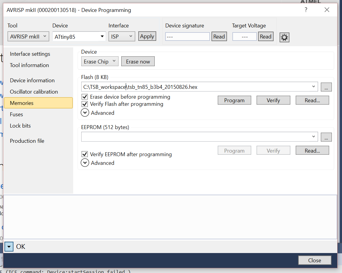
Then hit Program. With luck, your bootloader will burn and there will be much rejoicing.
To make sure the bootloader was burned correctly connect your ATtiny85 directly to a USB-to-UART. Open a serial terminal and connect at any baud rate 9600. Hit reset on the ATtiny85 and then quickly (within 2 seconds) send the @ in the serial-terminal. If the bootloader has been burned the ATtiny85 should reply with TSB followed by device data.
Wirelessly uploading
Here’s the fun part. I hooked up my ATtiny85, 2 x HM-10 modules, and an FTDI chip to a PC–like below,
To see if you everything is working, open a serial terminal program. I’m a little partial to this one: HM-1X Aid. Connect the your USB-to-UART using the serial terminal at 9600bps. Once you are connected, press the reset button on your ATtiny85 and send the character @ from your terminal several times. If everything is setup correctly the chip should reply with, TSB followed by device information. If it doesn’t reply, a few things to check.
- Test your wireless connection. I had to make sure the Bluetooth devices had paired and the Bluetooth device connected to the ATtiny was baud setting was less than 115200.
- Make sure your fuses are set correctly. Especially,
SELFPRGEN on the ATtiny, since it doesn’t come from the factory set.
Uploading an Arduino Sketch Wirelessly
Ok, if you were able to get the bootloader to reply wirelessly it’s time to test the whole setup. Open your Arduino and make sure you have install support for the ATtiny85,
Then, in your Arduino IDE select,
- Board: ATtiny
- Processor: ATtiny85
- Clock: 8mhz (internal)
Add this test sketch,
void setup() {
  // put your setup code here, to run once:
  for(int i = 0; i < 9; i++){
    pinMode(i, OUTPUT);
  }
}

void loop() {
  // put your main code here, to run repeatedly:
  int pin = 0;
  for(int i = 0; i < 9; i++){
    digitalWrite(i, HIGH);
  }
  delay(500);
  for(int i = 0; i < 9; i++){
    digitalWrite(i, LOW);
  }
  delay(500);
}
Still in the Arduino IDE go to Sketch--->Export compiled Binary. Save the hex file to your TSB Workspace. Open your TSB Workspace in the command prompt and type the following, replacing the COM port # with COM port you have the USB-to-UART on and replace the file name with the name of your newly compiled hex file.
C:\TSB_Workspace\tsb com4:9600 fw name_of_sketch.hex
Hit the RESET button on your ATtiny85 and then hit enter on your PC. If all goes as planned the command line will change to “Reading” and “Writing” appropriately. When the file has been uploaded, reset your ATtiny85. After a few seconds each pin on the ATtiny85 should go HIGH for half a second and then go LOW for half a second. If you don’t have an LED or MM, open your serial terminal again, connect to the COM port with your wireless setup, your serial terminal should receive the character, “0x00” every half a second.
Other baud rates work. But I found anything over 38400 to be unstable.
That’s it. Let me know what questions you have.
The future
Now there is a way to upload hex files wirelessly to a large array of chips, I plan to try a few things,
- Write an uploader in C# which could handle controlling a PIN on the HM-1X remotely which would pull the ATtiny85’s (or other chip) reset line low. This would allow me to wirelessly set the chip into bootloader mode.


 There is an issue with the HighlightJS module where the text escapes the divs. It took a long time to find the culprit. Apparently, the HighlightJS modules causes this whenever it renders HTML produced by CKEditor.