
Originally posted on www.letsmakerobots.com
NOTE: Try as I might, guys, I can't get the numbers to line up in my HTML version of my code. Instead, you might just load it into Geany or Notepad+ to follow along, since I indicated things by the line number. I'm sorry, I'm out of patience for it.
These are redneck instructions on how to control a robot with a static webcam for under 50 USD.
I'm a robot builder and I got tired of seeing universities play robot soccer or something with computer vision guiding their players, and no matter how much I begged, darn Ivy Leagues wouldn't share.
So, I wrote my own. And while I did it, I swore I'd try to help anyone trying something similar.

So, here's an overview of how the code works:
- Webcam sends images of its field-of-view.
- OpenCV looks for the largest red blob.
- It begins tracking the red blob's X, Y.
- The PC averages these X, Y positions for around 150 camera frames.
- If the blob hasn't moved much, the PC assumes the red blob is the robot.
- The PC gets frisky and gives our robot a random target within the webcam's field-of-view.
- The PC calculates the angle between the bot and the target.
- Meanwhile, the robot's microcontroller is taking readings from a magnetometer on the robot.
- The robot, with a one time human calibration, translates true North to "video-game north," aka, top of PC's screen.
- The microcontroller transmits this code to the PC.
- The PC compares the angle of the bot from the target with the robots angle.
- The PC sends a code to the bot telling it to turn left, right, or move forward (closer to the target).
- When the robot has made it within an acceptable distance from the target he "Munches the Dot."
- A new random dot appears. Rinse repeat. (For real though, don't rinse the bot. Consider Asimov's Third Law.)
About Me: (skip, it's boring)
I'm a homeless outreach worker. The job's amazing. But I'll say, emotionally taxing. Skipping the politics and the sermon on harm-reduction , I decided at the start I needed something far from the job to allow my mind rest and prevent compassion fatigue. Something that consumed my brain-power so I'd not be stressing over the 6 months pregnant 17 year-old, shooting up under a bridge on I-35. Something to protect my down-time so I'd be frosty for the next day.
Well, I saw that TED talk about the Sand Flea and I told Bek, "That's awesome, think I could build one?" "Oh crap," she said, "new obsession?"
Now, robots are my relief. My way to prevent white-matter from becoming dark-matter as I rake through sludge looking for those who want out.
I started reading a lot. I discovered, Arduino, Sparkfun, eBay, Raspberry Pi, ferric chloride , Python, hackaday , HC-SR04 , Eagle , OSHPark , and the list goes on. But every time I Googled something about robots, I'd end up at the same place.
These guys are brilliant. They are a college education from collaboration, I swear.
Soon, I ended up with my first bot. A piece of sh...short-circuits. Although, I did learn a lot interfacing the bot with the Raspberry Pi . Also, while I was working with a Raspberry Pi, I played with OpenCV , and was considering adding a face tracker to my bot before I got distracted. But before I quit, I created a proof-of-concept .
So, all these experiences began to culminate.
Meanwhile, I was taking a graduate Research Methods class at UTA and my professor disappeared. The university was amazing; good professors filled in and made sure our education didn't suffer. But we wondered for many months. Sadly, it was discovered he had killed himself.
It shook me. I deal with suicidality every other day, but it's usually on the street. Why a successful research professor? My thoughts got dark for a bit, which meant I sunk into robots even more. Yet, now, a question sat at the front of my mind: Will robots one day kill themselves?
This may sound silly. But I believe the formula for self-termination can be expressed in Boolean logic, and therefore coded.
Pseudo-code would be:
if painOfExistence > senseOfPurpose then:
self_terminate()
Derived from work and life experience I genuinely believe the root-motive for suicide is existential-anxiety , which seems to me, entangled within both constructs.
Ok. Skipping the _Time_bit.
Someday, I'd like to delve into swarm robotics. Or, at least, attempt to replicate organic group behavior within a robot group. And I thought it might be possible to control a group of robots with a setup similar to those universities or research groups keep showing off. (Jockish Ivy Leagues :P)
Well, I found these desires, information, and tools synergized into a passion. After two days, I was able to write a basic OpenCV Python script that could control a robot using a static webcam looking down on it. Let me clarify, I'm of average intelligence, simply obsessive, so when I mentioned "two-days" I'm trying to convey the utter feasibility of this project, for anyone . Python, Arduino, and OpenCV make it so very easy; anyidiot like me can hack it out.
Of course, my purpose for this platform is to control robot groups. The group being the second social collection (one-to-eight) and social interaction seems to be the essential in developing a positronic brain . The white-mattered brained being necessary for me to test the above mentioned self-termination formula. So, maybe, I'll learn if robots will commit suicide, or perhaps, have a better understanding of why humans do.
Dark and depressing! I know, right? Who writes this crap!?

A robot
It doesn't matter what sort of robot you use, it only needs:
- A microncontroller (e.g., Arduino , PicAxe , etc.)
- Built from material of a bold, solid color.
- The ability to change directions and move.
- A magnetometer. I used the HMC5883L . They're like 2 USD on eBay.
- A wireless serial connection. Bluetooth , Xbee , and nRF24L01 would be my recommendation since all are well documented creating a bridge between PC and microcontroller.
I personally built my own using red cutting-board I stole from Bek (shh). For my serial connection I used two $10 Bluetooth 4.0 modules, which I've written an instructable on setting up a Bluetooth 4.0 module to work with an Arduino and PC: Bluetooth 4.0 and Arduino .

A PC
Probably something less than 10 years old. It could be running Linux or Windows;though, I'll be using Windows Vista (hey, I'm first-world poor and can't afford Windows 7 :P).
- The PC will need to be running Python 2.7
- It'll need OpenCV 2.4.4
- It will need a wireless serial connection that pairs with your bot. Again, I used my BT 4.0 modules .

A Webcam
It's really up to you. I'm not going to lie, I went with the cheapest webcam I saw, which costs 6.87 USD. But I would _not _recommend this webcam. It didn't like my PC, so every time my Python script stopped I had to unplug the webcam and re-plug it in. A real annoyance for debugging.
- I'd suggest a high-resolution webcam. Maybe even a IP cam, if you're rich? If you are, would you buy me one too?
- Long male-to-female USB cable. Again, I got two 15' USB cables on eBay for around 4.50 USD. If you get everything setup and you notice problems with the webcam at the end of the cable, you can put a powered hub at the end of the cable with an extension cord and it'll take care of the issue. Though, I didn't have this problem at 15'.
- A wife that'll let you screw your webcam into the ceiling. Or...don't ask...
So, I made my robot, Dot Muncher , using an Arduino Uno , Motor Shield , and a Bluetooth 4.0 module . The chassis was made from HDPE , a cutting board I stole from my wife. The motors and tires were from eBay.
Now, about any robot will work, like I've stated, so Google away and select a robot build you like.
Of course, everything you'd every want to know can be found one this site :)
I'm just sayin'.
But the code, that's the part we want to focus on. Really, our robot only has a nerves and muscles, the brain will actually be in the PC, all the robot does is,
- Calculates the compass info.
- Sends the compass info to the PC.
- Reads the movement codes from the PC.
- Translates the movement code received into a motor activation.
That's it. Pretty simple.
//I've been using Zombie_3_6_RC in Processing to interact.


// Reference the I2C Library
#include <Wire.h>
// Reference the HMC5883L Compass Library
#include <HMC5883L.h>

// Store our compass as a variable.
HMC5883L compass;

// Record any errors that may occur in the compass.
int error = 0;

//int pwm_a = 10; //PWM control for motor outputs 1 and 2 is on digital pin 10
int pwm_a = 3;  //PWM control for motor outputs 1 and 2 is on digital pin 3
int pwm_b = 11;  //PWM control for motor outputs 3 and 4 is on digital pin 11
int dir_a = 12;  //dir control for motor outputs 1 and 2 is on digital pin 12
int dir_b = 13;  //dir control for motor outputs 3 and 4 is on digital pin 13

int lowspeed = 120;
int highspeed = 140;

//Distance away
int distance;

//Sets the duration each keystroke captures the motors.
int keyDuration = 10;

int iComp;

void setup()
{
  Serial.begin(9600);

  Wire.begin(); // Start the I2C interface.

  Serial.println("Constructing new HMC5883L");
  compass = HMC5883L(); // Construct a new HMC5883 compass.

  Serial.println("Setting scale to +/- 1.3 Ga");
  error = compass.SetScale(1.3); // Set the scale of the compass
  error = compass.SetMeasurementMode(Measurement_Continuous); // Set the measurement mode to Continuous

  pinMode(pwm_a, OUTPUT);  //Set control pins to be outputs
  pinMode(pwm_b, OUTPUT);
  pinMode(dir_a, OUTPUT);
  pinMode(dir_b, OUTPUT);

  analogWrite(pwm_a, 0);
  //set both motors to run at (100/255 = 39)% duty cycle (slow)
  analogWrite(pwm_b, 0);

  pinMode (2,OUTPUT);//attach pin 2 to vcc
  pinMode (5,OUTPUT);//attach pin 5 to GND
  // initialize serial communication:
  Serial.begin(9600);

}

void loop()
{


  // Retrive the raw values from the compass (not scaled).
  MagnetometerRaw raw = compass.ReadRawAxis();

  // Retrived the scaled values from the compass (scaled to the configured scale).
  MagnetometerScaled scaled = compass.ReadScaledAxis();

  // Values are accessed like so:
  int MilliGauss_OnThe_XAxis = scaled.XAxis;// (or YAxis, or ZAxis)

  // Calculate heading when the magnetometer is level, then correct for signs of axis.
  float heading = atan2(scaled.YAxis, scaled.XAxis);

  // Once you have your heading, you must then add your 'Declination Angle', which is the 'Error' of the magnetic field in your location.
  // Find yours here: http://www.magnetic-declination.com/
  // Mine is: 237' W, which is 2.617 Degrees, or (which we need) 0.0456752665 radians, I will use 0.0457
  // If you cannot find your Declination, comment out these two lines, your compass will be slightly off.
  float declinationAngle = 0.0457;
  heading += declinationAngle;

  // Correct for when signs are reversed.
  if(heading < 0)
    heading += 2*PI;

  // Check for wrap due to addition of declination.
  if(heading > 2*PI)
    heading -= 2*PI;

  // Convert radians to degrees for readability.
  float headingDegrees = heading * 180/M_PI;

  // Normally we would delay the application by 66ms to allow the loop
  // to run at 15Hz (default bandwidth for the HMC5883L).
  // However since we have a long serial out (104ms at 9600) we will let
  // it run at its natural speed.
  // delay(66);

  //This throttles how much data is sent to Python code.
  //Basically, it updates every second (10 microsecond delay X 100 iComps)
  if (iComp >= 30){

    int adjHeading = 0;
    //The "floor" part makes the float into an integer, rounds it up.
    headingDegrees = floor(headingDegrees);
    if (headingDegrees >= 280){
        adjHeading = map(headingDegrees, 280, 360, 0, 79);
    }
    else if (headingDegrees <= 279) {
        adjHeading = map(headingDegrees, 0, 279, 80, 360);
    }

    Serial.println(adjHeading);
    iComp=0;
  }
  iComp++;

  delay(10); //For serial stability.


  int val = Serial.read() - '0';

  if (val == 1)
  {
    Back();
  }

  else if (val == 2)
  {
    Right();
  }

  else if (val == 3)
  {
    Forward();
  }

  else if (val == 4)
  {
    Left();
  }

  else if (val == 5)
  {
    Stop();
  }
}

void Back(){
//Straight back
      analogWrite(pwm_a, highspeed);
      analogWrite(pwm_b, highspeed);

      digitalWrite(dir_a, HIGH);  //Reverse motor direction, 1 high, 2 low
      digitalWrite(dir_b, LOW);  //Reverse motor direction, 3 low, 4 high

delay(keyDuration);
}

void Left(){
      //Left
      analogWrite(pwm_a, lowspeed);
      analogWrite(pwm_b, lowspeed);

      digitalWrite(dir_a, HIGH);  //Reverse motor direction, 1 high, 2 low
      digitalWrite(dir_b, HIGH);  //Reverse motor direction, 3 low, 4 high

delay(keyDuration);
}

void Right(){
      //Right
      analogWrite(pwm_a, lowspeed);
      analogWrite(pwm_b, lowspeed);

      digitalWrite(dir_a, LOW);  //Reverse motor direction, 1 high, 2 low
      digitalWrite(dir_b, LOW);  //Reverse motor direction, 3 low, 4 high

delay(keyDuration);
}

void Forward(){
  //set both motors to run at 100% duty cycle (fast)
  analogWrite(pwm_a, highspeed);
  analogWrite(pwm_b, highspeed);

  //Straight forward
  digitalWrite(dir_a, LOW);  //Set motor direction, 1 low, 2 high
  digitalWrite(dir_b, HIGH);  //Set motor direction, 3 high, 4 low

  delay(keyDuration);
}

void Stop(){
  //set both motors to run at 100% duty cycle (fast)
  analogWrite(pwm_a, 0);
  analogWrite(pwm_b, 0);

  //Straight forward
  digitalWrite(dir_a, LOW);  //Set motor direction, 1 low, 2 high
  digitalWrite(dir_b, HIGH);  //Set motor direction, 3 high, 4 low

  delay(keyDuration);
}
The first bit of robot code I'd like to focus on is the compass. Now, I've not detailed how to use the HMC5883L , since SparkFun has done this for me. I also won't go into tilt-compensation , since I was more worried about proving the concept here than dead-on accuracy. But if you're a smart-cookie and would like to take that chaellenge, feel free. Just be sure and share the code with us all when you're done :P
No. Instead, I want to focus on adjusting the compass heading from a value respective to true North, to what we want it to think is north, in our case, whatever is the top of our screen. This process takes a little involvement, since the numbers must be set manually and with a little guesstimation.
See code above.
So, I got my compass module lying flat as possible and then bolted it to my robot. This helps assure your getting a full 360º and will keep you from having to re-calibrate what we'd like to call north every time the compass module gets knocked out of place.
106-114: These modules and the Arduino library are both designed to have 0º be North, but we want to set our own north, video-game north. Which is exactly what lines 106-114 are about. I found 80º is what value my robot was reading when he was headed towards the top of the screen. I had to find a way to adjust this to give me the reading 0º. I ended with this simple code to spin the compass.
I had to divide the adjustments into two sections for the math to stay simple. Lines 109-111 handle mapping 0-79º onto 280-0º, making the robot think 0-79º is 280-0º. Lines 112-114 do the same for 80-360º, converting it to 0-279º.
Honestly, I've got some spatial-retardation, so I have a hard time thinking through this, I just know it works . So, if you have problems I'll answer emails and Skypes and we can work through it together. And, if you want to submit a better explanation, I'll post it and be sure to give you credit.

Do know, my redneck solution was to change the orientation of the camera. Pfft. Too easy .
Moving on,
116: Sends the robot's heading to the PC.
117: iComp is a variable allowing us to decide when to start sending data to the PC. We don't want to send data to the PC before it's ready or before the robot is warmed-up, we'd be dealing with poor readings.
118: This is a delay that makes sure we are not bogging down the serial line, since every time we call Serial.println("whatever") both the PC and the robot have to take some processing power to deal with it. In short, it's to make sure the robot is not talking the computer's ear off.
See code above.
This bit is pretty easy. It reads the codes being sent from the PC and translates them into a function call. I write all my robot-PC interactions this way, since if I want a code to mean something completely different, for instance I want to swap the robot's right and left movements, I'd just swap lines 134 and 144.
Easy.
125: If I remember correctly, this line reads serial data being sent from the PC and assures the val variable isn't getting a bunch of zeros.
Easy one.
This is one of the functions called to make the motor move, or in the case of this function, stop.
188-189: This actually tells which pin on the Arduino, specified by the variables pwm_a and pwm_b to decrease to 0. This effectively stops our robot.
192-193: This bit actually tells the motor which direction to turn. The pins ( dir_a and dir_b) are set either HIGH or LOW and this changes the direction of how the motor moves.
Tell you what, my good friend ChickenParmi explains it better here
See code above.
Now we have a our little robot setup, let's setup our Python environment.
I'm going to use Python 2.7 (just found later versions piss me off).
For windows, use the MSI Install respective to your architecture, either x86 or x64. Of course, Linux and Mac are versions are there as well. Go ahead and install Python 2.7, but I'm not a fan of their IDE . Instead, I use:
Though, this IDE is a little tricky to get running on Windows, since it's meant for Linux. These posts over at Stack Overflow go through some popular Windows Python IDEs. Pick what you feel comfortable in. I suggest running 'Hello World' in each until you decide you like one.
Here we are, the hardest part of this whole project; if not careful, we fall into dependency hell .
I'm going to try and help you setup all the modules needed to run the Python code. It's been difficult for me to do this right, so I'll try to be descriptive.
There are seven modules we will use.
Of these we will need to install OpenCV, Numpy, and Serial, since the rest come built into Python 2.7.
The main trick with any module you install in Python is to make sure the exact path you install it to gets added to the Environment Variable (this is true for both Windows and Linux).
To explain this I'm going to hand it over to Lovely Ada as she tells us how to install the Serial module:
pySerial installation
Note the bit about adding the environment variable, since none of the other modules will explain this, but each will need to be there.
Now, let's try OpenCV and Numpy. My favorite installation guide (meaning it worked for me) was written by Abid Rahman :
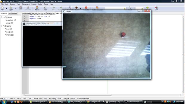
At this point, you might bring up Python and try some simple webcam capture test code (if you have problems copying and pasting, I've added web capture code as an attachment as well):
See code above.
If you see a live feed from your webcam, you're almost good to go.

If there any problems, like I said, you and me buddy. Feel free to ask questions here or Skype me: thomas_ladvien
Okay. Here's all the Python code in one go. _Don't be scared _if this looks confusing. I feel the same way. In fact, some of it I _still _don't understand. (Hey, honesty a is a rare fault I seem to possess.) Again, don't worry, we're going to walk through it one section at a time, you and me, buddy. Until the end.
On the flip side, if you are a Python guru, or yanno, just a sassy-pants: Feel free to add corrections and comments on this page. I'd love to make this code grow through critique. Do know, I guarantee the following: Typos, grammar problems, illogical coding, artifacts from debugging, and the like. But don't worry, I'm thick skinned and usually wear my big-boy panties.
I should state, the basic code for color tracking was written by Abid Rahman in a reply on Stack Overflow .
Also, I've included the code as an attachment, it's at the bottom. Video-game south.
See code above.
Ok. The beginning.
So lines 3-10 pull in the modules we will need. My take on a module is the following, "Code some smart guy wrote and doesn't want anymore, so he gave it to me to use."
To be specific
- cv2 is the OpenCV module.
- Numpy , which we'll call " np " throughout the code, is used for higher number functions needed for OpenCV to do her magic.
- Serial is the module which will allow us to establish a serial connection between the PC and the robot, via whichever wireless device you've chosen.
- Time allows us to basically idle the code. This is important in controlling many things, for instance, how far the robot moves. We tell the motors to turn on, wait 10 secs, then turn off. Because the sleep function actually puts the code into an idle state, we must have the threading module, since our code requires the PC to do several things at once.
- Math . From the math module we get the code to help us simplify the trigonometry calculations, like the angle between the robot and target.
- The random module is only used to gives us a random target.
-
Threading
. Important module. Basically, threading allows the computers to do two tasks at the same time. This becomes important when we are both trying to track the robot and receive his position. Throughout this code we will have three threads
- The thread running the OpenCV stuff. This tracks the robot and is also the largest.
- A thread controlling the serial connection between the robot and PC.
- And a thread with the small job of telling the motors how long to be on, thereby controlling how far the robot will move.
See code above.
13: This is where we actually open a serial connection to the wireless device you are using. Note, we've named the serial connection we opened " ser " so when we go to send information it will be something like, ser.write("What you want to send here")
15-38: Here we declare a bunch of variables. The " global variable " lets the code know that this variable is going to jump between all threads. Next, the variable = 0 actually declares the variable. Do know, you'll have to remind each thread a variable is global by stating "global variable."
One thing I should state, iFrame = 0 is an actual variable declaration, as well as setting it to 0. Of course, this is how one would declare an integer variable with an initial value of 0. On the flip, rx = " " isalso a variable declaration but this time a string. You'll know I switched information from a integer to a string if you see something like this:
headingDeg = str(intHeadingDeg)
That tells the code, "I want to convert the value in intHeadingDeg, which is an integer, into a string and call it 'headingDeg'"
The comments indicate what each variable is meant for. Not going to lie, not sure I don't have some declared variables I meant to use, didn't, and forgot to remove.
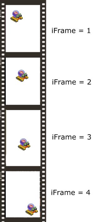
One important variable is the iFrame variable, since it tracks which frame we are on. This becomes key in all aspects of tracking our robot.
See code above.
42 : Here we start this function that does most of the work, OpenCV(): . It is one of the functions that will be threaded at lines 345-347 .
44 : We open up the webcam and give it the nickname cap . If I remember right the "0" in the parenthesis refers to whatever camera comes first on your USB bus, so if you have more than one camera you can specify by changing this number, e.g., cap = cv2.VideoCapture(3) . Notice we called the OpenCV module cv2, so we are using the OpenCV module to access the webcam.
46-52 : Just making the variables we declared work within this function. This might not be needed, but hey, I don't read the whole Python manual.
55: This is just a string flag that is flipped to tell the PC to generate a new target for the robot. Note, we initially set it to "Yes" meaning the first time we run through this function a target needs to be generated.
58: This is an integer variable to count how many dots the robot has "ate."
Ok, before I get to the next bit I need to take a minute and explain how we approach actually getting the coordinates of our robot. As you know, OpenCV does the hard work for us, giving us the X and Y coordinate of the largest red blob on the screen. Though, the coordinates it gives us are the center of the mass. Now, this is all just a logical guess because I didn't read the whole OpenCV manual, but I believe the X or Y coordinate that refers to the center of this mass is called the centroid .

This might seems simple. That's because it is, I'm not sure why we don't just call it the damn center or something. Eh, oh well. Though, it will become important when we do collision detection between the robot and its target.
61-62 : All that to say, the "c" in cyAvg and cxAvg stands for centroid. So, these are variables that will hold the running average for the X and Y coordinates of the red blob's centroid.
65-66: These are back-up variables of the cxAvg and cyAvg and will be important around line 122-127 when we are trying to decide if the color we are tracking is actually the robot or some other piece of junk with enough red in it to fool OpenCV.
69: This simply clears the string variable with data that came from the robot, like the robot's heading, before another iFrame starts.
See code above.
71 : Creates a loop within the OpenCV() function.
73-81: Ok, I need to be humble here and say I'm not sure what the Cthulhu's Kitchen I was doing. I know printRx = str(intRx) is taking the information received from the robot and converting it into a string. intRx is as a global variable and it is loaded with robot data at line 326. headingDeg = printRx is moving the heading data from one variable to another; the idea here was if I wanted more information to come from the robot besides the compass heading it would come in through printRx , then I could chop it up and load it into variables respective to their purpose.
For instance, printRx.split(",") should give a list of strings based on how many commas are currently held within printRx.
printRx = "2, 23, 88" compass, sonar, battery_life = printRx.split(",")
Now,
compass = 2 sonar = 23 battery_life = 88
But the part that confuses me is I turn right back around and convert the string back to an integer? I'm not sure, guys. I might have Southpark while coding again.
At the end of that poor coding we end up with two variables to use: intHeadingDeg and headingDeg. We the integer intHeadingDeg to do any calculations that involve the robot's heading. The other, headingDeg , is to print the robot's heading to the screen, which is done at line 263.
84-85: These are string variables that will will hold the "Target Locked X" or "Target Locked Y" if we are tracking the robot. These strings are needed so we can print this to the screen on line 259-260.
See code above.
We're in the meat now.
88: This increments our frame counter.
91: We read a single frame from the webcam we declared, cap, at line 44.
OPENCV! Sorry, I just love it so much.
So, by now you know I've not read the OpenCV manual. And please don't tell me, "What! Go RTFM !" You go RTFM! I've got a wife, kid, and a job I love. I'm just going to tinker with crap and get it to work. But this attitude will begin to show as we go through the OpenCV calls, since I don't know their inner working. Instead, I'm going to offer my best guess, and as always, if someone wants to correct me or offer better explanation, I'll post and give credit.
94: This blurs the image we got. You may say, "But I thought higher resolution was better?" It is. But jagged edges and color noise are not. A simple shape is much easier for math of OpenCV to wrap around then a complex one. Therefore, we blur the image a little, giving us softer edges to deal with.
Also, blur melds colors, so if there are 2 blue pixels and 1 red pixel in a group, then it become 3 blue-purplish pixels. This has the nifty benefit of speeding up the image processing a lot . How much? I don't know I didn't RTFM.
97-100: Our image is converted to a histogram here. Having the image in a histogram format allows us to use comparative statements with it. What we use it for is to get rid of all the colors except the one we are trying to find. This will give us a black and white image, the white being only the color we are looking to find.**Line 98 is where your color is defined (it's the two "np.array"s).
In the next step I'll go through how to select your robot's exact color.**

103: Finds the contours of the white area in the resulting image.

107-112: OpenCV then counts how many pixels are in each contour it finds in the webcam image. It assumes whichever has the most white area (aka, "mass") is our object.

114-117: After we decided which object we want to track, now we need to come up with the centroid coordinates. That is what lines 115-116 do. I've not done the research on the math there, but I believe it averages the moments of the polygon and calls the average either centroid X or Y, depending on the calculation. But, feel free to correct or explain better.

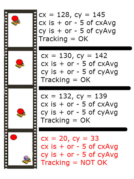
121-127:
Here we lock onto the mass we believe is the robot. It begins by collecting a 150 samples before it will state is tracking the largest mass. But after it begins to track the largest mass, then we try to stay locked on to it. This is line 122-127. In essence, we allow the mass to move enough to be considered a movement by the robot, but not so much that noise (like a stray hand in the webcam image) will cause the tracking to switch off the robot.
See code above.
This particular line defines what color you are looking for, specifically, the two sets of values: 130, 170, 110 and 190, 190, 200. These two values set the lower limit and the upper limit of the color you are looking to find. The reason we use upper and lower limits, which we'll call color thresholds, is because our robot will move through different lights. Different light sources have a tendency to change how the webcam reads the color.
The color format we are using is HSV, which stands for hue, saturation, value . Later, I'll probably write code to select the robot within our actual program, but for now I use Gimp and the following method:
- Setup your webcam the in the area you'll be using, just like you're ready to control him.
-
Run the webcam program attached in step 10.
- While the webcam program is watching your robot, hit Ctrl + Print Screen
- Open Gimp.
-
Hit Ctrl + V to paste the screen capture into gimp.
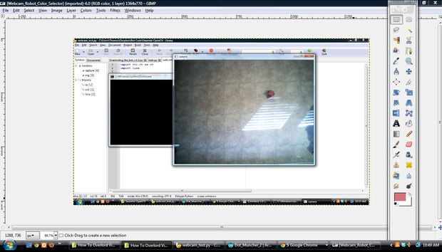
-
Now, find the Color Selector tool.
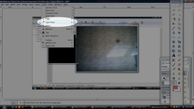
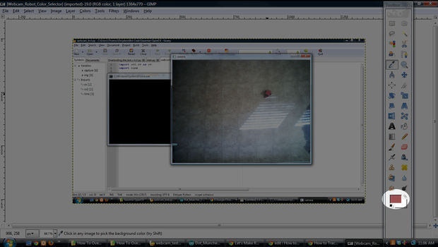
- Select the main color of your robot.
-
Now double click on the color square on the toolbar.
-
A window should pop open with color information regarding the color you selected, your robot.
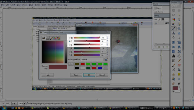
- Now, the three numbers listed should be close to what we need. Sadly, we have to convert from Gimp's HSV number range to OpenCV's HSV number range. You see, HSV value range in Gimp is H = 0- 360, S = 0-100, and V = 0-100. In OpenCV, H = 0-180, S = 0-255, V = 0-255. So, some conversion needs to take place.
- From my selection I ended with Gimp numbers of, H: 355, S:50, and V:61. I could get all fancy and calculate the right numbers, but I figure 180 (OpenCV) is half of 360, so for my H I just divided by two: 177. The other two I kinda guess at a little. I doubled and added 25, S: 125 and V: 147.
- In the end, this gave me middle numbers. But I wanted an upper and lower threshold, so I took each number and subtracted 20 to give me a lower, and added 20 to give me an upper.
- The result for my robot was:


See code above.
I'll try to code a color selector into the program to make this whole damn thing a cinch.
If you'd like to read more, two good posts on Stack Overflow.
See code above.
132-136: Here we actually take the running average of the centroids' X and Y. We load this into the variables cxAvg and cyAvg , again, this is to assure we are tracking the robot.
142-145 : Here the target, or "dot," for the robot to run after is randomly generated. As you may notice I restricted the generation area of the dots towards the center of my webcam's field-of-view. That's because I'm messy and dots were going where the little robot couldn't get.
147-153: This is a rough collision detection function. Basically, if the robot gets so close to the target (45px) then it has considered to have "eaten" the dot. If it did, then the dot variable is incremented showing the total amount he's done ate and the newTarget string variable is flipped so it can generate a new target the next run through.
See code above.
156-177: Here we are trying to find the angle between the robot and his target. We basically divide the entire screen up into four quadrants but always using the robot's centroid as the point of origin. We then calculate the slope between the target's X and Y ( tY , tX ) and the robot's X and Y ( cxAvg and cyAvg ).
Something like this:

If the target were to be located in the quadrant III, it would go something like this.

See code above.
181: When we find the angle between the robot and the target, then convert it into degrees, it ends up giving us a number which is a float . That's more than we need, so here we convert the float ( degs) to and integer (targetDegs) so we can compare to the robot's compass heading.
184: We declare an empty string called strTargetDegs . 187: Then we convert the float degs into a string so we can print the target angle onto the screen at line 264.
See code above.
This is where I need help guys. My turning code has a bug, so if you find it and come up with a correction I'll send you a prize. I dunno? A lint ball? It'd probably be one of my left over circuit boards, or some piece of hardware I hacked together.
But for now, let's take a look.
The idea is like:

The code is supposed to go as follows:
if target1 = True then:
MoveForward()
elif target2 = True then:
TurnRight()
elif target3 = True then:
TurnLeft()
And for the most part that happens, but occasionally it is dumb and turns left when it should right. Not sure what I'm doing wrong. Hey, that "You and me buddy, until the end" is a two-way street. :P
Let's step through it
195: We want to make sure we are deep into tracking the robot before we start moving it towards the target.
198: We compare intHeadingDeg , which is the robot's heading angle, with targetDegs, which is the angle between the robot and the target. But we do this + or - 30º. This means the robot does not have to have its heading angle exactly the same as the angle to the target it. It only need to be approximately pointing in the right direction.
199: The movement code for the robot to go forward is 3 , so here, given the robot is approximately headed in the right direction, we tell the robot to move forward. This happens by loading 3 into the variable tranx, which is transmitted to the robot at line 307. When this code gets transmitted to my robot, the Arduino code at line 137 tells the Forward(); function to fire.
202: If our robot isn't headed in the right direction, then which way should he turn?
203-232: Still debugging here. I'm sorry guys. I can tell you this code works "Ok." But once I'm done with this tutorial, I'll go back and focus on making it turn perfect. Sorry, this code took me two days to right, but this tutorial has taken too many days.
Though, within each of the if statements we have two variable assignments: tranx = X and motorDuration = 10 . The tranx tells the robot which direction to move and the motorDuration tells it how long to move that way (this is not yet being utilized in my code).
See code above.
Here, we are drawing every thing to the screen before we show the frame.
242: Red circle for target.
247: White box to display black text on. Note, we are drawing things bottom up. So, if you want something to have a particular Z level you'll need to put it towards the top of this section.
250: This is the green line between the target and our robot.
253-267: We display all our info here. Compass heading, target-lock, etc.
270: This actually shows the color window (the window we wrote everything on).
271: This shows the HSV copy of the captured frame. Notice the white area to be assessed as our target.
See code above.
276: An if-statement that waits for the ESC to be pressed. If it gets pressed, we close stuff.
278: This releases our webcam.
279: This closes the windows we were displaying the color and HSV frames.
281: We send the code to stop our robot. If we don't do this and we hit the ESC in the middle of a robot movement, that move will continue forever.
282: Here we closed the serial connection.
283: We quit.
Towards the beginning of this article I stated my webcam had crappy drivers; well, while writing this I noticed I had placed the cv2.destroyAllWindows before cap.release(). This is what was causing the problem. My interpretation of this was our camera being sucked into the void where the destroyed windows go. Anyway, I switched the order and it seems to have solved the problem.
See code above.
Finally, we are opening our second threaded function. This function is much smaller than the OpenCV function. Here all serial communication takes place.
289: This helps in translating ASCII.
292-296: Global variables for passing robot information to other threads.
See code above.
303: We read information into the variable rx . The information is coming from the serial line we opened at the code's beginning.
307: This is a flag gate that makes it where our Python code can only send a motor command to the robot if the robot isn't already in the middle of a movement.
308: We write whatever value is in tranx , which should be loaded with some sort of movement from lines 192-232.
313: I think I threw this in there so the serial-line would bog down the my code.
316: We strip the number down to three digits only;remember, this is the compass heading in degrees, e.g, 000-360 º.
319: When something is sent over serial it gets an end-of-line character. We don't want that.
323: The robot collected this number from a compass, which gave a number with a decimal involved. This removes the decimal so we are only dealing with whole numbers.
326-329: I'm not sure what I was doing here, I think it had to do with the oddities of zero. Eh. I'll try to remember.
See code above.
This is a short threaded function. It only really has one job, to control how long the motors on the robot stay on. It works like this, if we send the robot a message to move forward, it continues to do so until line 341. There, the command to stop is sent to the robot and the motorBusy flag is set back to "No" meaning the motor is ready to be used again.
340: This sets how long the motor will stay on. For instance, if it were changed to sleep(1) the robot's motor would continue in the direction they were told for 1 second.
342: This makes the robot wait in between movements. In theory, this was meant to ensure OpenCV could keep up with the little guy. So, if you have a fast robot, you might set this higher.
See code above.
Ok. Code's End.
This bit starts all three threads: OpenCV , rxtx , and motorTimer.
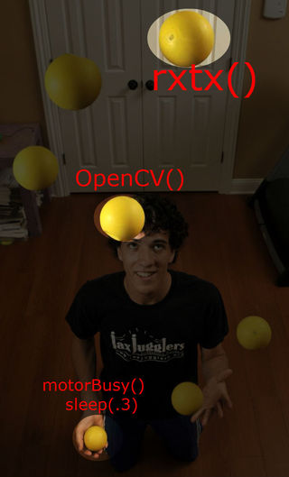
And here is my poor attempt to explain Python threading. Most Python code is run sequentially; the order it comes is the order it is executed. One problem is timing. If we have to cause a delay in code, then the whole program has to pause. Threading allows us to get around this. I see it like a juggler performing that trick where he keeps all the balls going in one hand, while he holds one ball still in his other. I dunno, just how I see it.
 Well, like I said,
"You and me, buddy, until the end."
And here we are. The end.**
Well, like I said,
"You and me, buddy, until the end."
And here we are. The end.**
I hope this code has been helpful. But do know, you're not alone.
cthomasbrittain@hotmail.com
Skype: thomas_ladvien**
Skype or email me if you have any questions. Likewise, all that crap I did a poor job explaining, coding, writing, just shoot me an email and I'll fix it.
I still want to develop this into a Swarmie platform; so you might keep an eye out on www.letsmakerobots.com since I'll post my unfinished work there. Alright, I'm off to work on the 8th iteration of my Swarmie...ugh.